從零開始建造一個vue項目

準備工作

環境依賴:Node.js; vue官方腳手架:  vue-cli

具體怎麼安裝nodejs和vue-cli的部分就不再具體說明了,請查看官方文檔按步驟執行即可(安裝nodejs會安裝npm(包管理工具),vue-cli依賴npm來安裝,注意這個先後關係)。

背景知識

vue.js核心  框架

webpack  打包工具,使用vue-cli初始化項目的時候,我們選擇webpack作為我們的模塊打包工具

開始動手

初始化項目,選擇webpack作為打包工具,項目名稱是my-project,然後按照提示進行一些配置,過程中可以選擇使用vue-router(推薦使用);這些配置最終會寫到項目的package.json中和安裝相應的模塊

vue init webpack my-project
复制代码

接下來使用自己熟悉的編輯器打開項目,目錄結構大致是這樣的

構建和配置目錄:webpack打包的相關配置文件

src目錄:我們最終編寫業務代碼的地方

static目錄:我也不知道幹嘛用的

package.json

package.json是項目最基礎的配置文件。可以發現裡面的很多內容,例如名稱,作者,描述等就是剛才初始化項目時我們填充的值; dependencies和devDependencies是項目依賴的包,運行項目之前需要先執行npm install來安裝項目所依賴的包

npm install复制代码

然後我們來重點關註一下scripts

npm允許在package.json文件裡面,使用scripts分區定義腳本命令。其中dev和start都是啟動本地開發環境的,lint是做語法校正的,build是打包最終在線代碼的

{
  "name": "my-project",
  "version": "1.0.0",
  "description": "A Vue.js project",
  "author": "ideagay <[email protected]>",
  "private": true,
  "scripts": {
    "dev": "webpack-dev-server --inline --progress --config build/webpack.dev.conf.js",
    "start": "npm run dev",
    "lint": "eslint --ext .js,.vue src",
    "build": "node build/build.js"
  },
  "dependencies": {
    "vue": "^2.5.2",
    "vue-router": "^3.0.1"
  },
  "devDependencies": {...},
  "engines": {
    "node": ">= 6.0.0",
    "npm": ">= 3.0.0"
  },
  "browserslist": [
    "> 1%",
    "last 2 versions",
    "not ie <= 8"
  ]
}

复制代码

為了統一團隊內的代碼風格,我們一般會選擇一些語法校驗插件來實現代碼風格的統一。這裡我們選擇eslint作為我們的代碼檢查插件。首先我們來改一下eslint(語法校驗)的相關配置, :根目錄下的.eslintrc.js,在規則下面加一個結尾分號的配置,強制末尾要加分號,養成好習慣;然後把src下面所有文件裡的代碼所在分號的補全,不然編譯會不通過;其他風格根據習慣自己配置吧。

"semi": [
  2,
  "always"
]复制代码

運行項目看下效果

:命令行工具,在當前目錄下執行以下命令,一切順利的話,會自動打開在瀏覽器上打開localhost:8080

# 默认8080端口
npm run dev

# 也可以指定端口
PORT=8090 npm run dev复制代码

添加業務代碼

src目錄是我們主要編寫業務代碼的地方,可參考以下目錄結構配置

資產js,css,圖片等資源目錄

組件公共組件目錄

路由器vue-router配置目錄

views頁面組件目錄

main.js程序主入口,一般在這裡添加插件,如吐司,裝載等,可自己編寫或使用第三方,如ui

App.vue根組件

main.js

import Vue from 'vue';
import App from './App';
import ElementUI from 'element-ui';
import 'element-ui/lib/theme-chalk/index.css';
import router from './router';

Vue.config.productionTip = false;

Vue.use(ElementUI);

/* eslint-disable no-new */
new Vue({
  el: '#app',
  router,
  components: { App },
  template: '<App/>'
});复制代码

路由

往router / index.js裡添加首頁的配置

import Vue from 'vue';
import Router from 'vue-router';
import Home from '@/views/index';

Vue.use(Router);

export default new Router({
  routes: [
    {
      path: '/',
      name: 'home',
      component: Home
    }
  ]
});复制代码

網絡請求

網絡請求可以使用axios,然後根據業務再進行一些封裝

資產/js/api/ajax.js

import axios from 'axios';
var qs = require('qs');

var instance = axios.create({
   baseURL: 'http://xxx.com/',
   timeout: 20000,
   headers: {
      'Content-Type': 'application/x-www-form-urlencoded'
   }
});

const ajax = (url, params) => {
   return new Promise((resolve, reject) => {
      instance({
         url: url,
         method: 'post',
         data: qs.stringify(params)
      }).then(res => {
         console.log(res);
         if (res.data.success === true) {
            resolve(res.data.data);
         } else {
            throw res;
         }
      }).catch(err => {
         console.error(err);
         reject(err);
      })
   })
};

export default ajax;复制代码
import Ajax from '@/assets/js/api/ajax.js';
Ajax(`/tui/search`, {
   'key': this.keyword
}).then(res => {
   console.log(res);
});
复制代码

樣式

使用normalize.css重置基礎樣式,消除不同瀏覽器間的差異,在根組件App.vue中約會就好了

<script>
import 'normalize.css';

export default {
   name: 'App'
}
</script>复制代码

現在一般業務所需的框架已經基本建造完成。

作者:ideagay
链接:https://juejin.im/post/5a7c18d36fb9a0633e51c458
来源:掘金
著作权归作者所有。商业转载请联系作者获得授权,非商业转载请注明出处。

How to Use MQTT With the Raspberry Pi and ESP8266

How to Use MQTT With the Raspberry Pi and ESP8266

In this Instructable, I will explain what the MQTT protocol is and how it is used to communicate between devices.Then, as a practical demonstration, I shall show you how to setup a simple two client system, where an ESP8266 module will send a message to a Python program when a button is pushed. Specifically, I am using an Adafruit HUZZAH module for this project, a Raspberry Pi and a desktop computer. The Raspberry Pi will be acting as the MQTT broker, and the Python client will be run from a separate desktop computer (optional, as this could be run on the Raspberry Pi).

To follow along with this Instructable, you will need to have some basic knowledge of electronics, and how to use the Arduino software. You should also be familiar with using a command line interface (for the Raspberry Pi). Hopefully, once you’ve gained the knowledge of what MQTT is, and how to use it in a basic scenario, you will be able to create your own IoT projects!

Required Parts

  • 1 x Raspberry Pi, connected to a local network (running Jessie)
  • 1 x ESP8266 Module (Adafruit HUZZAH)
  • 1 x Breadboard
  • 3 x Jumper Wires (Male-to-Male)
  • 1 x Pushbutton
  • 1 x 10k Ohm Resistor (Brown-Black-Orange colour code)

I’ve created this Instructable, as MQTT has always interested me as a protocol and there are many different ways it could be used. However, I couldn’t seem to get my head around how to code devices to use it. This was because I didn’t know/understand what was actually going on to take my “Hello, World!” from device A and send it to device B. Hence, I decided to write this Instructable to (hopefully) teach you how it works, and to also reinforce my own understanding of it!


Step 1: What Is MQTT?

What Is MQTT?

MQTT, or MQ Telemetry Transport, is a messaging protocol which allows multiple devices to talk to each other. Currently, it is a popular protocol for the Internet of Things, although it has been used for other purposes – for example, Facebook Messenger. Interestingly MQTT was invented in 1999 – meaning it’s as old as me!

MQTT is based around the idea that devices can publish or subscribe to topics. So, for example. If Device #1 has recorded the temperature from one of its sensors, it can publish a message which contains the temperature value it recorded, to a topic (e.g. “Temperature”). This message is sent to an MQTT Broker, which you can think of as a switch/router on a local area network. Once the MQTT Broker has received the message, it will send it to any devices (in this case, Device #2) which are subscribed to the same topic.

In this project, we will be publishing to a topic using an ESP8266, and creating a Python script that will subscribe to this same topic, via a Raspberry Pi which will act as the MQTT Broker. The great thing about MQTT is that it is lightweight, so it perfect for running on small microcontrollers such as an ESP8266, but it is also widely available – so we can run it on a Python script as well.

Hopefully, at the end of this project, you will have an understanding of what MQTT is and how to use it for your own projects in the future.

Step 2: Installing the MQTT Broker on the Raspberry Pi

Installing the MQTT Broker on the Raspberry Pi

To setup our MQTT system, we need a broker, as explained in the previous step. For the Raspberry Pi, we will be using the “Mosquitto” MQTT broker. Before we install this, it is always best to update our Raspberry Pi.

sudo apt-get update
sudo apt-get upgrade

Once you’ve done this, install mosquitto and then the mosquitto-clients packages.

sudo apt-get install mosquitto -y
sudo apt-get install mosquitto-clients -y

When you’ve finished installing these two packages, we are going to need to configure the broker. The mosquitto broker’s configuration file is located at /etc/mosquitto/mosquitto.conf, so open this with your favourite text editor. If you don’t have a favourite text editor or don’t know how to use any of the command line editors, I’ll be using nano so you can follow along:

sudo nano /etc/mosquitto/mosquitto.conf

At the bottom of this file, you should see the line:

include_dir /etc/mosquitto/conf.d

Delete this line. Add the following lines to the bottom of the file.

allow_anonymous false
password_file /etc/mosquitto/pwfile
listener 1883

By typing those lines, we’ve told mosquitto that we don’t want anyone connecting to our broker who doesn’t supply a valid username and password (we’ll get on to set these in a second) and that we want mosquitto to listen for messages on port number 1883.

If you don’t want the broker to require a username and password, don’t include the first two lines that we added (i.e. allow_anonymous… and password_file…). If you have done this, then skip to rebooting the Raspberry Pi.

Now close (and save) that file. If you are following along with the nano example, press CTRL+X, and type Y when prompted.

Because we’ve just told mosquitto that users trying to use the MQTT broker need to be authenticated, we now need to tell mosquitto what the username and password are! So, type the following command – replacing username with the username that you would like – then enter the password you would like when prompted (Note: if, when editing the configuration file, you specified a different password_file path, replace the path below with the one you used).

sudo mosquitto_passwd -c /etc/mosquitto/pwfile username

As we’ve just changed the mosquitto configuration file, we should reboot the Raspberry Pi.

sudo reboot

Once the Raspberry Pi has finished rebooting, you should have a fully functioning MQTT broker! Next, we are going to try to interact with it, using a number of different devices/methods!

Step 3: Testing the Broker

Testing the Broker

Once you’ve installed mosquitto on the Raspberry Pi, you can give it a quick test – just to make sure everything is working correctly. For this purpose, there are two commands that we can use on the command line. mosquitto_pub and mosquitto_sub. In this step, I will guide you through using each of these to test our broker.

In order to test the broker, you will need to open two command line windows. If you are using Putty or another SSH client, this is as simple as opening another SSH window and logging in as usual. If you are accessing your Pi from a UNIX terminal, this is exactly the same. If you are using the Raspberry Pi directly, you will need to open two terminal windows in the GUI mode (the command startxcan be used to start the GUI).

Now that you have opened two windows, we can get started on the testing. In one of the two terminals, type the following command, replacing username and password with the ones you setup in the previous step.

mosquitto_sub -d -u username -P password -t test

If you decided not to set a username and password in the previous step, then from now on, ignore the -u and -P flags in the commands. So, as an example, the mosquitto_sub command would now be:

mosquitto_sub -d -t test

The mosquitto_sub command will subscribe to a topic, and display any messages that are sent to the specified topic in the terminal window. Here, -d means debug mode, so all messages and activity will be output on the screen. -u and -P should be self-explanatory. Finally, -t is the name of the topic we want to subscribe to – in this case, “test”.

Next, in the other terminal window, we are going to try and publish a message to the “test” topic. Type the following, remembering again to change username and password:

mosquitto_pub -d -u username -P password -t test -m "Hello, World!"

When you press enter, you should see your message “Hello, World!” appear in the first terminal window we used (to subscribe). If this is the case, you’re all set to start working on the ESP8266!

Step 4: Setting Up the ESP8266 (Adafruit HUZZAH)

Setting Up the ESP8266 (Adafruit HUZZAH)

This step if specific to the Adafruit HUZZAH (as that is what I am using to complete this project). If you are using a different Arduino / ESP8266 device, you may wish to skip this step. However, I would advise you skim read it, just in case there is any information here that may be relevant to you.

For this project, I am going to be programming the HUZZAH with the Arduino software. So, if you haven’t already, make sure to install the Arduino software (newer than 1.6.4). You can download it here.

Once you have installed the Arduino software, open it and navigate to File->Preferences. Here you should see (near the bottom of the window) a text box with the label: “Additional Boards Manager URLs”. In this text box, copy and paste the following link:

http://arduino.esp8266.com/stable/package_esp8266com_index.json

Click OK to save your changes. Now open the Board Manager (Tools->Board->Board Manager) and search for ESP8266. Install the esp8266 by ESP8266 Community package. Restart the Arduino software.

Now, before we can program the board, we need to select a few different options. In the Tools menu option, select Adafruit HUZZAH ESP8266 for Board, 80 MHz for the CPU Frequency (you can use 160 MHz if you wish to overclock it, but for now I’m going to use 80 MHz), 4M (3M SPIFFS) for the Flash Size, and 115200 for the Upload Speed. Also, make sure to select the COM port that you are using (this will depend on your setup).

Before you can upload any code, you need to make sure that the HUZZAH is in bootloader mode. To enable this, hold down the button on the board marked GPIO0, and whilst this is held, hold down the Reset button as well. Then, release the Reset button, and then GPIO0. If you have done this correctly, the red LED that came on when you pressed GPIO0 should now be dimly lit.

To upload code to the microcontroller, first make sure the HUZZAH is in bootloader mode, then simply click the upload button in the Arduino IDE.

If you are having any trouble setting up the HUZZAH, further information can be found at Adafruit’s own tutorial.

Step 5: Programming the ESP8266

Programming the ESP8266

Now we will begin to program the ESP8266, but before we can start, you will need to install the following libraries in the Arduino Library manager (Sketch->Include Libraries->Manage Libraries)

  • Bounce2
  • PubSubClient

Once you’ve installed those libraries, you will be able to run the code I’ve included in this Instructable (MQTT_Publish.zip). I’ve made sure to comment it so that you can understand what each section is doing, and this should hopefully enable you to adapt it to your needs.

Remember to change the constants at the top of the code so that your ESP8266 can connect to your WiFi network and your MQTT Broker (the Raspberry Pi).

If you decided not to set a username and password for the MQTT Broker, then download the MQTT_PublishNoPassword.zip file instead.

Attachments

Step 6: Installing Python Client (paho-mqtt)

Installing Python Client (paho-mqtt)

Thankfully, this step is very simple! To install the mosquitto python client, you just need to type the following into the command line (Linux/Mac) or even command prompt (Windows).

pip install paho-mqtt

Note: Windows command prompt may have an issue running the pip command if you didn’t specify that you wanted pip installed and python added to your PATH variable when you installed Python. There are a number of ways of fixing this, but I think just reinstalling Python is the easiest way. If in doubt – give it a google!

Step 7: Python Client – Subscribing

Python Client - Subscribing

In this step, we are going to setup the Python script (either on the Raspberry Pi itself or on another computer connected to the network) to handle all of the messages that are sent (published) by the ESP8266 to the MQTT topic.

I have included the python code below (PythonMQTT_Subscribe.py), which has been commented to help you understand what is going on, but I will explain some of the main features here as well.

If you didn’t set a username and password for the MQTT connection earlier, download the PythonMQTT_SubscribeNoPassword.py file instead.

Attachments

Step 8: Communicating Between ESP8266 Devices

Communicating Between ESP8266 Devices

If you want to set up an IoT network, for example, you may wish to communicate between ESP8266 devices. Thankfully, this isn’t much more complex than the code we’ve written before, however, there are a couple of notable changes.

For one ESP to send data to another, the first ESP will need to publish to the topic, and the second ESP will need to subscribe to that topic. This setup will allow for a one-way conversation – ESP(1) to ESP(2). If we want ESP(2) to talk back to ESP(1), we can create a new topic, to which ESP(2) will publish, and ESP(1) will subscribe. Thankfully, we can have multiple subscribers on the same topic, so if you want to send data to a number of systems, you will only need one topic (to which they all subscribe, except the device which is sending the data, as that will be publishing).

If you need help figuring out what each device needs to do, think about the system as a room of people. If ESP(1) is publishing, you can imagine this device as a “speaker”, and any devices that are subscribing to the topic are “listeners” in this example.

I have included some example code below, which demonstrates how an ESP8266 can subscribe to a topic, and listen for certain messages – 1 and 0. If 1 is received, the on-board LED (for the HUZZAH – GPIO 0) is switched on. If 0 is received, this LED is switched off.

If you want to process more complex data, this should be done in the ReceivedMessage function (see code).

For your own projects, if you need to both send and receive data, you can incorporate the publish function from the previous example into the code included in this step. This should be handled in the main Arduino loop() function.

Remember to change the variables at the top of the code to suit your network!

IoT based Smart Irrigation System using Soil Moisture Sensor and ESP8266 NodeMCU

IoT based Smart Irrigation System using Soil Moisture Sensor and ESP8266 NodeMCUIoT based Smart Irrigation System using Soil Moisture Sensor and ESP8266 NodeMCU

Most of the farmers use large portions of farming land and it becomes very difficult to reach and track each corner of large lands. Sometime there is a possibility of uneven water sprinkles. This result in the bad quality crops which further leads to financial losses. In this scenario the Smart Irrigation System using Latest IoT technology is helpful and leads to ease of farming.

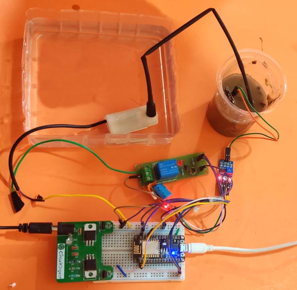
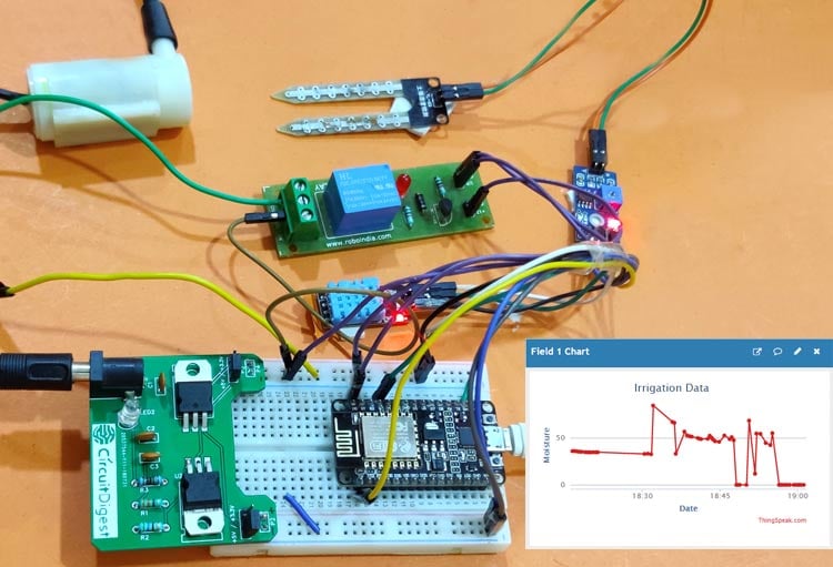
The Smart irrigation System has wide scope to automate the complete irrigation system. Here we are building a IoT based Irrigation System using ESP8266 NodeMCU Module and DHT11 Sensor. It will not only automatically irrigate the water based on the moisture level in the soil but also send the Data to ThingSpeak Server to keep track of the land condition. The System will consist a water pump which will be used to sprinkle water on the land depending upon the land environmental condition such as Moisture, Temperature and Humidity.

We previously build similar Automatic Plant Irrigation System which sends alerts on mobile but not on IoT cloud. Apart from this, Rain alarm and soil moisture detector circuit can also be helpful in building Smart Irrigation system.

Before starting, it is important to note that the different crops require different Soil Moisture, Temperature and Humidity Condition. So in this tutorial we are using such a crop which will require a soil moisture of about 50-55%. So when the soil loses its moisture to less than 50% then Motor pump will turn on automatically to sprinkle the water and it will continue to sprinkle the water until the moisture goes upto 55% and after that the pump will be turned off. The sensor data will be sent to ThingSpeak Server in defined interval of time so that it can be monitored from anywhere in the world.

Components Required

  • NodeMCU ESP8266
  • Soil Moisture Sensor Module
  • Water Pump Module
  • Relay Module
  • DHT11
  • Connecting Wires

You can buy all the components required for this project.

Circuit Diagram

Circuit diagram for this IoT Smart Irrigation System is given below:
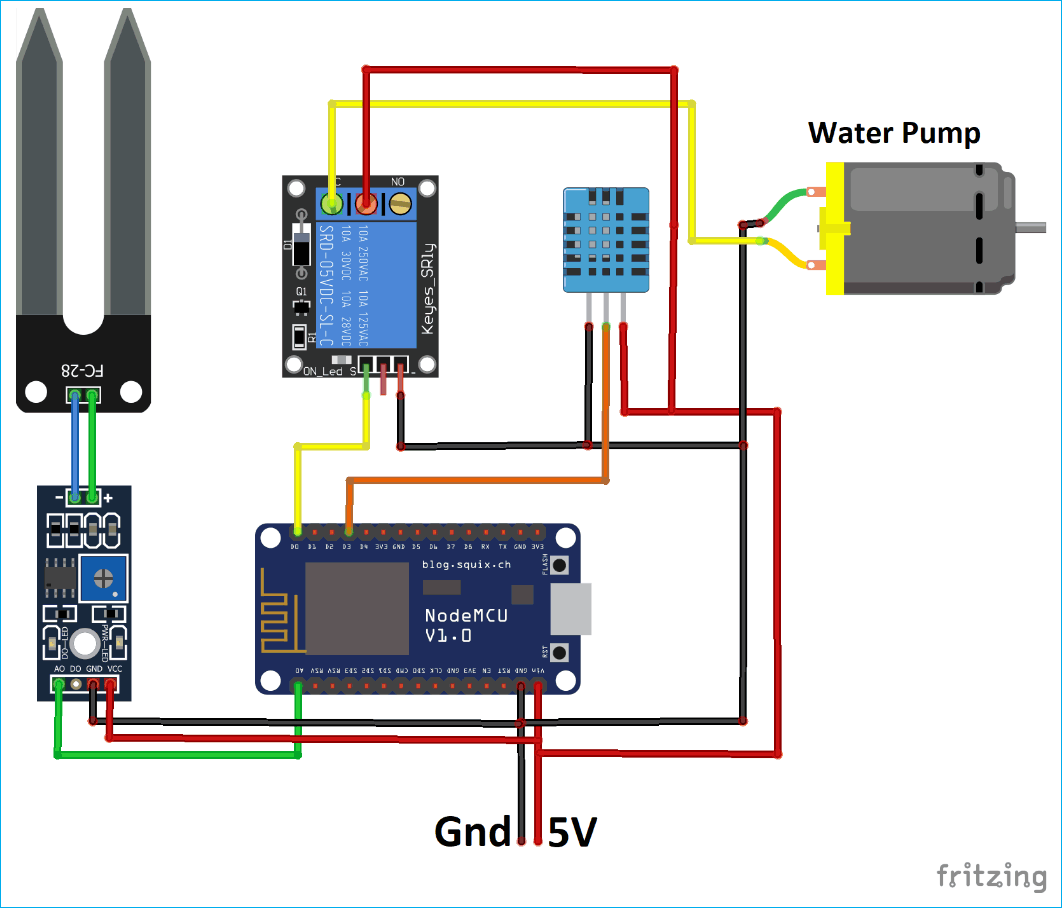
Circuit Diagram for IoT based Smart Irrigation System using Soil Moisture Sensor and ESP8266 NodeMCU

Circuit Hardware for IoT based Smart Irrigation System using Soil Moisture Sensor and ESP8266 NodeMCU

Programming ESP8266 NodeMCU for Automatic Irrigation System

For programming the ESP8266 NodeMCU module, only the DHT11 sensor library is used as external library. The moisture sensor gives analog output which can be read through the ESP8266 NodeMCU analog pin A0. Since the NodeMCU cannot give output voltage greater than 3.3V from its GPIO so we are using a relay module to drive the 5V motor pump. Also the Moisture sensor and DHT11 sensor is powered from external 5V power supply.

Complete code with a working video is given at the end of this tutorial, here we are explaining the program to understand the working flow of the project.

Start with including necessary library.

#include <DHT.h>
#include <ESP8266WiFi.h>

Since we are using the ThingSpeak Server, the API Key is necessary in order to communicate with server. To know how we can get API Key from ThingSpeak you can visit previous article on Live Temperature and Humidity Monitoring on ThingSpeak.

String apiKey = "X5AQ445IKMBYW31H
const char* server = "api.thingspeak.com"; 

The next Step is to write the Wi-Fi credentials such as SSID and Password.

const char *ssid =  "CircuitDigest";     
const char *pass =  "xxxxxxxxxxx"; 

Define the DHT Sensor Pin where the DHT is connected and Choose the DHT type.

#define DHTPIN D3          
DHT dht(DHTPIN, DHT11);

The moisture sensor output is connected to Pin A0 of ESP8266 NodeMCU. And the motor pin is connected to D0 of NodeMCU.

const int moisturePin = A0;
const int motorPin = D0;

We will be using millis() function to send the data after every defined interval of time here it is 10 seconds. The delay() is avoided since it stops the program for a defined delay where microcontroller cannot do other tasks. Learn more about the difference between delay() and millis() here.

unsigned long interval = 10000;
unsigned long previousMillis = 0;

Set motor pin as output, and turn off the motor initially. Start the DHT11 sensor reading.

pinMode(motorPin, OUTPUT);
digitalWrite(motorPin, LOW); // keep motor off initally
dht.begin();

Try to connect Wi-Fi with given SSID and Password and wait for the Wi-Fi to be connected and if connected then go to next steps.

WiFi.begin(ssid, pass);
  while (WiFi.status() != WL_CONNECTED)
  {
    delay(500);
    Serial.print(".");
  }
  Serial.println("");
  Serial.println("WiFi connected");
}

Define the current time of starting the program and save it in a variable to compare it with the elapsed time.

unsigned long currentMillis = millis();

Read temperature and humidity data and save them into variables.

float h = dht.readHumidity();
float t = dht.readTemperature();

If DHT is connected and the ESP8266 NodeMCU is able to read the readings then proceed to next step or return from here to check again.

if (isnan(h) || isnan(t))
  {
    Serial.println("Failed to read from DHT sensor!");
    return;
  }

Read the moisture reading from sensor and print the reading.

moisturePercentage = ( 100.00 - ( (analogRead(moisturePin) / 1023.00) * 100.00 ) );
  Serial.print("Soil Moisture is  = ");
  Serial.print(moisturePercentage);
  Serial.println("%");

If the moisture reading is in between the required soil moisture range then keep the pump off or if it goes beyond the required moisture then turn the pump ON.

if (moisturePercentage < 50) {
    digitalWrite(motorPin, HIGH);
  }
   if (moisturePercentage > 50 && moisturePercentage < 55) {
    digitalWrite(motorPin, HIGH);
  }
 if (moisturePercentage > 56) {
    digitalWrite(motorPin, LOW);
  }

Now after every 10 seconds call the sendThingspeak() function to send the moisture, temperature and humidity data to ThingSpeak server.

  if ((unsigned long)(currentMillis - previousMillis) >= interval) {
    sendThingspeak();
    previousMillis = millis();
    client.stop();
  }

In the sendThingspeak() function we check if the system is connected to server and if yes then we prepare a string where moisture, temperature, humidity reading is written and this string will be sent to ThingSpeak server along with API key and server address.

if (client.connect(server, 80))
    {
      String postStr = apiKey;
      postStr += "&field1=";
      postStr += String(moisturePercentage);
      postStr += "&field2=";
      postStr += String(t);
      postStr += "&field3=";
      postStr += String(h);      
      postStr += "\r\n\r\n";

Finally the data is sent to ThingSpeak server using client.print() function which contains API key, server address and the string which is prepared in previous step.

client.print("POST /update HTTP/1.1\n");
      client.print("Host: api.thingspeak.com\n");
      client.print("Connection: close\n");
      client.print("X-THINGSPEAKAPIKEY: " + apiKey + "\n");
      client.print("Content-Type: application/x-www-form-urlencoded\n");
      client.print("Content-Length: ");
      client.print(postStr.length());
      client.print("\n\n");
      client.print(postStr);

Finally this is how the data looks on ThingSpeak Dashboard
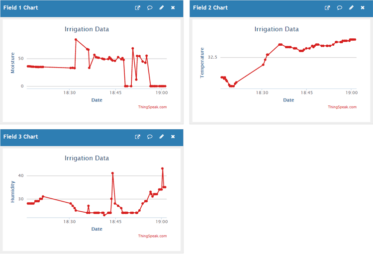
Getting Data on ThingSpeak for IoT based Smart Irrigation System

This last step finishes the complete tutorial on IoT based Smart Irrigation System. Note that it is important to switch off the motor when the soil moisture has reached the required level after water sprinkle. You can make a more smart system which can contain different control for different crops.

If you face any issues while doing this project then comment below or reach to our forums for more relevant questions and their answers.

Find the complete program and demonstration Video for this project below.

Code

#include <DHT.h>
#include <ESP8266WiFi.h>
String apiKey = “X5AQ3EGIKMBYW31H”;     //  Enter your Write API key here
const char* server = “api.thingspeak.com”;
const char *ssid =  “CircuitLoop”;     // Enter your WiFi Name
const char *pass =  “circuitdigest101”; // Enter your WiFi Password
#define DHTPIN D3          // GPIO Pin where the dht11 is connected
DHT dht(DHTPIN, DHT11);
WiFiClient client;

const int moisturePin = A0;             // moisteure sensor pin
const int motorPin = D0;
unsigned long interval = 10000;
unsigned long previousMillis = 0;
unsigned long interval1 = 1000;
unsigned long previousMillis1 = 0;
float moisturePercentage;              //moisture reading
float h;                  // humidity reading
float t;                  //temperature reading

void setup()
{
Serial.begin(115200);
delay(10);
pinMode(motorPin, OUTPUT);
digitalWrite(motorPin, LOW); // keep motor off initally
dht.begin();
Serial.println(“Connecting to “);
Serial.println(ssid);
WiFi.begin(ssid, pass);
while (WiFi.status() != WL_CONNECTED)
{
delay(500);
Serial.print(“.”);              // print … till not connected
}
Serial.println(“”);
Serial.println(“WiFi connected”);
}

void loop()
{
unsigned long currentMillis = millis(); // grab current time

h = dht.readHumidity();     // read humiduty
t = dht.readTemperature();     // read temperature

if (isnan(h) || isnan(t))
{
Serial.println(“Failed to read from DHT sensor!”);
return;
}

moisturePercentage = ( 100.00 – ( (analogRead(moisturePin) / 1023.00) * 100.00 ) );

if ((unsigned long)(currentMillis – previousMillis1) >= interval1) {
Serial.print(“Soil Moisture is  = “);
Serial.print(moisturePercentage);
Serial.println(“%”);
previousMillis1 = millis();
}

if (moisturePercentage < 50) {
digitalWrite(motorPin, HIGH);         // tun on motor
}
if (moisturePercentage > 50 && moisturePercentage < 55) {
digitalWrite(motorPin, HIGH);        //turn on motor pump
}
if (moisturePercentage > 56) {
digitalWrite(motorPin, LOW);          // turn off mottor
}

if ((unsigned long)(currentMillis – previousMillis) >= interval) {

sendThingspeak();           //send data to thing speak
previousMillis = millis();
client.stop();
}

}

void sendThingspeak() {
if (client.connect(server, 80))
{
String postStr = apiKey;              // add api key in the postStr string
postStr += “&field1=”;
postStr += String(moisturePercentage);    // add mositure readin
postStr += “&field2=”;
postStr += String(t);                 // add tempr readin
postStr += “&field3=”;
postStr += String(h);                  // add humidity readin
postStr += “\r\n\r\n”;

client.print(“POST /update HTTP/1.1\n”);
client.print(“Host: api.thingspeak.com\n”);
client.print(“Connection: close\n”);
client.print(“X-THINGSPEAKAPIKEY: ” + apiKey + “\n”);
client.print(“Content-Type: application/x-www-form-urlencoded\n”);
client.print(“Content-Length: “);
client.print(postStr.length());           //send lenght of the string
client.print(“\n\n”);
client.print(postStr);                      // send complete string
Serial.print(“Moisture Percentage: “);
Serial.print(moisturePercentage);
Serial.print(“%. Temperature: “);
Serial.print(t);
Serial.print(” C, Humidity: “);
Serial.print(h);
Serial.println(“%. Sent to Thingspeak.”);
}
}

ADS1115 analog-to-digital converter and ESP8266

The ADS1115 device is a precision, low-power, 16-bit, I2C-compatible, analog-to-digital converters (ADCs) offered in an ultra-small, leadless, X2QFN-10 package, and a VSSOP-10 package. The ADS1115 device incorporates a low-drift voltage reference and an oscillator. The ADS1115 also incorporate a programmable gain amplifier and a digital comparator. These features, along with a wide operating supply range, make the ADS1115 well suited for power- and space-constrained, sensor measurement applications.

The ADS1115 perform conversions at data rates up to 860 samples per second (SPS). The PGA offers input ranges from ±256 mV to ±6.144 V, allowing precise large- and small-signal measurements. The ADS1115 features an input multiplexer  that allows two differential or four single-ended input measurements. Use the digital comparator in the ADS1115 for under- and overvoltage detection.

The ADS1115 operates in either continuous-conversion mode or single-shot mode. The devices are automatically powered down after one conversion in single-shot mode; therefore, power consumption is significantly reduced during idle periods.

Features

Wide Supply Range: 2.0 V to 5.5 V
Low Current Consumption: 150 µA
(Continuous-Conversion Mode)
Programmable Data Rate: 8 SPS to 860 SPS
Single-Cycle Settling
Internal Low-Drift Voltage Reference
Internal Oscillator
I2C Interface: Four Pin-Selectable Addresses
Four Single-Ended or Two Differential Inputs (ADS1115)
Programmable Comparator (ADS1114 and ADS1115)
Operating Temperature Range: –40°C to +125°C

Parts List

This module will cost less than $2

Amount Part Type
1 ADS1115
1 Wemos D1 mini V2


Schematics/Layout


In the layout below we just show basic connection between Wemos Mini and ADS1115 – you can add a pot, connect an LDR to one of the A0 – A3 inputs of the ADS1115

esp8266 and ads1115
esp8266 and ads1115


Code

Again we use a library and again its an adafruit one – https://github.com/adafruit/Adafruit_ADS1X15

#include <Wire.h>
#include <Adafruit_ADS1015.h>
 
Adafruit_ADS1115 ads(0x48);
 
void setup(void)
{
Serial.begin(9600);
Serial.println("Hello!");
 
Serial.println("Getting single-ended readings from AIN0..3");
Serial.println("ADC Range: +/- 6.144V (1 bit = 3mV/ADS1015, 0.1875mV/ADS1115)");
 
ads.begin();
}
 
void loop(void)
{
int16_t adc0, adc1, adc2, adc3;
 
adc0 = ads.readADC_SingleEnded(0);
adc1 = ads.readADC_SingleEnded(1);
adc2 = ads.readADC_SingleEnded(2);
adc3 = ads.readADC_SingleEnded(3);
Serial.print("AIN0: ");
Serial.println(adc0);
Serial.print("AIN1: ");
Serial.println(adc1);
Serial.print("AIN2: ");
Serial.println(adc2);
Serial.print("AIN3: ");
Serial.println(adc3);
Serial.println(" ");
 
delay(1000);
}


Links

http://www.ti.com/lit/ds/symlink/ads1115.pdf

I2C ADS1115 16 Bit ADC 4 channel Module with Programmable Gain Amplifier 2.0V to 5.5V RPi