 IoT based Smart Irrigation System using Soil Moisture Sensor and ESP8266 NodeMCU
Most of the farmers use large portions of farming land and it becomes very difficult to reach and track each corner of large lands. Sometime there is a possibility of uneven water sprinkles. This result in the bad quality crops which further leads to financial losses. In this scenario the Smart Irrigation System using Latest IoT technology is helpful and leads to ease of farming.
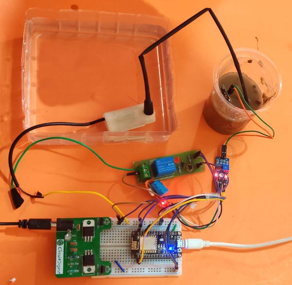
The Smart irrigation System has wide scope to automate the complete irrigation system. Here we are building a IoT based Irrigation System using ESP8266 NodeMCU Module and DHT11 Sensor. It will not only automatically irrigate the water based on the moisture level in the soil but also send the Data to ThingSpeak Server to keep track of the land condition. The System will consist a water pump which will be used to sprinkle water on the land depending upon the land environmental condition such as Moisture, Temperature and Humidity.
We previously build similar Automatic Plant Irrigation System which sends alerts on mobile but not on IoT cloud. Apart from this, Rain alarm and soil moisture detector circuit can also be helpful in building Smart Irrigation system.
Before starting, it is important to note that the different crops require different Soil Moisture, Temperature and Humidity Condition. So in this tutorial we are using such a crop which will require a soil moisture of about 50-55%. So when the soil loses its moisture to less than 50% then Motor pump will turn on automatically to sprinkle the water and it will continue to sprinkle the water until the moisture goes upto 55% and after that the pump will be turned off. The sensor data will be sent to ThingSpeak Server in defined interval of time so that it can be monitored from anywhere in the world.
Components Required
- NodeMCU ESP8266
- Soil Moisture Sensor Module
- Water Pump Module
- Relay Module
- DHT11
- Connecting Wires
You can buy all the components required for this project.
Circuit Diagram
Circuit diagram for this IoT Smart Irrigation System is given below:

Programming ESP8266 NodeMCU for Automatic Irrigation System
For programming the ESP8266 NodeMCU module, only the DHT11 sensor library is used as external library. The moisture sensor gives analog output which can be read through the ESP8266 NodeMCU analog pin A0. Since the NodeMCU cannot give output voltage greater than 3.3V from its GPIO so we are using a relay module to drive the 5V motor pump. Also the Moisture sensor and DHT11 sensor is powered from external 5V power supply.
Complete code with a working video is given at the end of this tutorial, here we are explaining the program to understand the working flow of the project.
Start with including necessary library.
#include <DHT.h>
#include <ESP8266WiFi.h>
Since we are using the ThingSpeak Server, the API Key is necessary in order to communicate with server. To know how we can get API Key from ThingSpeak you can visit previous article on Live Temperature and Humidity Monitoring on ThingSpeak.
String apiKey = "X5AQ445IKMBYW31H
const char* server = "api.thingspeak.com";
The next Step is to write the Wi-Fi credentials such as SSID and Password.
const char *ssid =  "CircuitDigest";
const char *pass =  "xxxxxxxxxxx";
Define the DHT Sensor Pin where the DHT is connected and Choose the DHT type.
#define DHTPIN D3
DHT dht(DHTPIN, DHT11);
The moisture sensor output is connected to Pin A0 of ESP8266 NodeMCU. And the motor pin is connected to D0 of NodeMCU.
const int moisturePin = A0;
const int motorPin = D0;
We will be using millis() function to send the data after every defined interval of time here it is 10 seconds. The delay() is avoided since it stops the program for a defined delay where microcontroller cannot do other tasks. Learn more about the difference between delay() and millis() here.
unsigned long interval = 10000;
unsigned long previousMillis = 0;
Set motor pin as output, and turn off the motor initially. Start the DHT11 sensor reading.
pinMode(motorPin, OUTPUT);
digitalWrite(motorPin, LOW); // keep motor off initally
dht.begin();
Try to connect Wi-Fi with given SSID and Password and wait for the Wi-Fi to be connected and if connected then go to next steps.
WiFi.begin(ssid, pass);
  while (WiFi.status() != WL_CONNECTED)
  {
    delay(500);
    Serial.print(".");
  }
  Serial.println("");
  Serial.println("WiFi connected");
}
Define the current time of starting the program and save it in a variable to compare it with the elapsed time.
unsigned long currentMillis = millis();
Read temperature and humidity data and save them into variables.
float h = dht.readHumidity();
float t = dht.readTemperature();
If DHT is connected and the ESP8266 NodeMCU is able to read the readings then proceed to next step or return from here to check again.
if (isnan(h) || isnan(t))
  {
    Serial.println("Failed to read from DHT sensor!");
    return;
  }
Read the moisture reading from sensor and print the reading.
moisturePercentage = ( 100.00 - ( (analogRead(moisturePin) / 1023.00) * 100.00 ) );
  Serial.print("Soil Moisture is  = ");
  Serial.print(moisturePercentage);
  Serial.println("%");
If the moisture reading is in between the required soil moisture range then keep the pump off or if it goes beyond the required moisture then turn the pump ON.
if (moisturePercentage < 50) {
    digitalWrite(motorPin, HIGH);
  }
   if (moisturePercentage > 50 && moisturePercentage < 55) {
    digitalWrite(motorPin, HIGH);
  }
 if (moisturePercentage > 56) {
    digitalWrite(motorPin, LOW);
  }
Now after every 10 seconds call the sendThingspeak() function to send the moisture, temperature and humidity data to ThingSpeak server.
  if ((unsigned long)(currentMillis - previousMillis) >= interval) {
    sendThingspeak();
    previousMillis = millis();
    client.stop();
  }
In the sendThingspeak() function we check if the system is connected to server and if yes then we prepare a string where moisture, temperature, humidity reading is written and this string will be sent to ThingSpeak server along with API key and server address.
if (client.connect(server, 80))
    {
      String postStr = apiKey;
      postStr += "&field1=";
      postStr += String(moisturePercentage);
      postStr += "&field2=";
      postStr += String(t);
      postStr += "&field3=";
      postStr += String(h);
      postStr += "\r\n\r\n";
Finally the data is sent to ThingSpeak server using client.print() function which contains API key, server address and the string which is prepared in previous step.
client.print("POST /update HTTP/1.1\n");
      client.print("Host: api.thingspeak.com\n");
      client.print("Connection: close\n");
      client.print("X-THINGSPEAKAPIKEY: " + apiKey + "\n");
      client.print("Content-Type: application/x-www-form-urlencoded\n");
      client.print("Content-Length: ");
      client.print(postStr.length());
      client.print("\n\n");
      client.print(postStr);
Finally this is how the data looks on ThingSpeak Dashboard
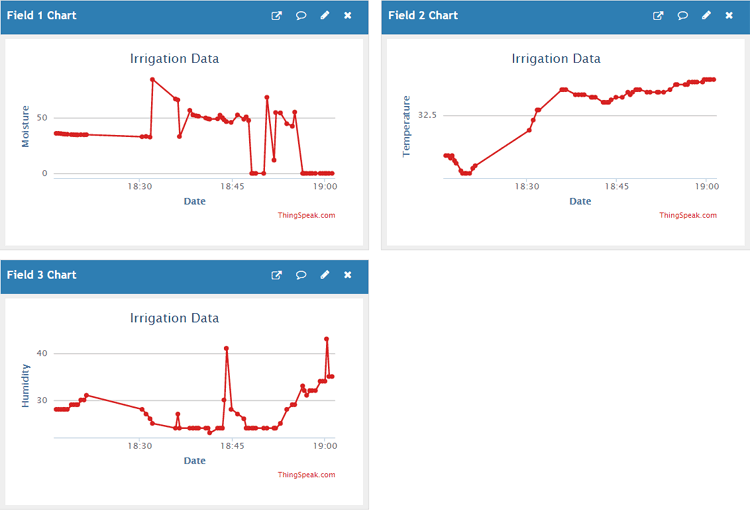
This last step finishes the complete tutorial on IoT based Smart Irrigation System. Note that it is important to switch off the motor when the soil moisture has reached the required level after water sprinkle. You can make a more smart system which can contain different control for different crops.
If you face any issues while doing this project then comment below or reach to our forums for more relevant questions and their answers.
Find the complete program and demonstration Video for this project below.
#include <DHT.h>
#include <ESP8266WiFi.h>
String apiKey = “X5AQ3EGIKMBYW31H”; // Enter your Write API key here
const char* server = “api.thingspeak.com”;
const char *ssid = “CircuitLoop”; // Enter your WiFi Name
const char *pass = “circuitdigest101”; // Enter your WiFi Password
#define DHTPIN D3 // GPIO Pin where the dht11 is connected
DHT dht(DHTPIN, DHT11);
WiFiClient client;
const int moisturePin = A0; // moisteure sensor pin
const int motorPin = D0;
unsigned long interval = 10000;
unsigned long previousMillis = 0;
unsigned long interval1 = 1000;
unsigned long previousMillis1 = 0;
float moisturePercentage; //moisture reading
float h; // humidity reading
float t; //temperature reading
void setup()
{
Serial.begin(115200);
delay(10);
pinMode(motorPin, OUTPUT);
digitalWrite(motorPin, LOW); // keep motor off initally
dht.begin();
Serial.println(“Connecting to “);
Serial.println(ssid);
WiFi.begin(ssid, pass);
while (WiFi.status() != WL_CONNECTED)
{
delay(500);
Serial.print(“.”); // print … till not connected
}
Serial.println(“”);
Serial.println(“WiFi connected”);
}
void loop()
{
unsigned long currentMillis = millis(); // grab current time
h = dht.readHumidity(); // read humiduty
t = dht.readTemperature(); // read temperature
if (isnan(h) || isnan(t))
{
Serial.println(“Failed to read from DHT sensor!”);
return;
}
moisturePercentage = ( 100.00 – ( (analogRead(moisturePin) / 1023.00) * 100.00 ) );
if ((unsigned long)(currentMillis – previousMillis1) >= interval1) {
Serial.print(“Soil Moisture is = “);
Serial.print(moisturePercentage);
Serial.println(“%”);
previousMillis1 = millis();
}
if (moisturePercentage < 50) {
digitalWrite(motorPin, HIGH); // tun on motor
}
if (moisturePercentage > 50 && moisturePercentage < 55) {
digitalWrite(motorPin, HIGH); //turn on motor pump
}
if (moisturePercentage > 56) {
digitalWrite(motorPin, LOW); // turn off mottor
}
if ((unsigned long)(currentMillis – previousMillis) >= interval) {
sendThingspeak(); //send data to thing speak
previousMillis = millis();
client.stop();
}
}
void sendThingspeak() {
if (client.connect(server, 80))
{
String postStr = apiKey; // add api key in the postStr string
postStr += “&field1=”;
postStr += String(moisturePercentage); // add mositure readin
postStr += “&field2=”;
postStr += String(t); // add tempr readin
postStr += “&field3=”;
postStr += String(h); // add humidity readin
postStr += “\r\n\r\n”;
client.print(“POST /update HTTP/1.1\n”);
client.print(“Host: api.thingspeak.com\n”);
client.print(“Connection: close\n”);
client.print(“X-THINGSPEAKAPIKEY: ” + apiKey + “\n”);
client.print(“Content-Type: application/x-www-form-urlencoded\n”);
client.print(“Content-Length: “);
client.print(postStr.length()); //send lenght of the string
client.print(“\n\n”);
client.print(postStr); // send complete string
Serial.print(“Moisture Percentage: “);
Serial.print(moisturePercentage);
Serial.print(“%. Temperature: “);
Serial.print(t);
Serial.print(” C, Humidity: “);
Serial.print(h);
Serial.println(“%. Sent to Thingspeak.”);
}
}

