ESP32 vs ESP8266 – Pros and Cons

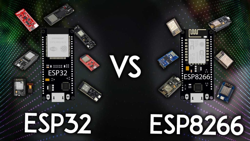
What’s the difference between ESP32 and ESP8266? Should you use the ESP32 or the ESP8266 in your projects? In this article, we’ll compare the ESP32 with the ESP8266 and cover the pros and cons of each board.

The ESP32 and ESP8266 are cheap Wi-Fi modules perfectly suited for DIY projects in the Internet of Things (IoT) and Home Automation fields.

Both chips have a 32-bit processor. The ESP32 is a dual-core 160MHz to 240MHz CPU, whereas the ESP8266 is a single-core processor that runs at 80MHz.

These modules come with GPIOs that support various protocols like SPI, I2C, UART, ADC, DAC, and PWM. The best part is that these boards come with wireless networking included, which makes them apart from other microcontrollers like the Arduino. This means that you can easily control and monitor devices remotely via Wi-Fi or Bluetooth (in the case of ESP32) for a very low price.

Alternatively, if you don’t need to use its wireless capabilities, you can use the ESP32/ESP8266 to control inputs and outputs as you would do with an Arduino. However, you should take into account that whereas the Arduino works with 5V logic, the ESP32 and ESP8266 work at 3.3V.

Specifications: ESP32 vs ESP8266

The ESP32 is the ESP8266 successor. It adds an extra CPU core, faster Wi-Fi, more GPIOs, and supports Bluetooth 4.2 and Bluetooth low energy. Additionally, the ESP32 comes with touch-sensitive pins that can be used to wake up the ESP32 from deep sleep, a built-in hall effect sensor, and a built-in temperature sensor (recent versions of the ESP32 don’t come with a built-in temperature sensor anymore).

Both boards are cheap, but the ESP32 costs slightly more. While the ESP32 can cost around $6 to $12, the ESP8266 can cost $4 to $6 (but it really depends on where you get them and what model you’re buying).

The following table shows the main differences between the ESP8266 and the ESP32 chips (table adapted from AMICA_IO).

ESP8266
ESP32
MCU
Xtensa Single-core 32-bit L106
Xtensa Dual-Core 32-bit LX6 with 600 DMIPS
802.11 b/g/n Wi-Fi
HT20
HT40
Bluetooth
X
Bluetooth 4.2 and BLE
Typical Frequency
80 MHz
160 MHz
SRAM
X
Flash
X
GPIO
17
34
Hardware /Software PWM
None / 8 channels
None / 16 channels
SPI/I2C/I2S/UART
2/1/2/2
4/2/2/2
ADC
10-bit
12-bit
CAN
X
Ethernet MAC Interface
X
Touch Sensor
X
Temperature Sensor
X
(old versions)
Hall effect sensor
X
Working Temperature
-40ºC to 125ºC
-40ºC to 125ºC
Price
$ (3$ – $6)
$$ ($6 – $12)
Where to buy

Using ESP32 or ESP8266 bare chips is not easy or practical, especially when testing and prototyping. Most of the time, you’ll want to use ESP32 and ESP8266 development boards. These boards come with all the needed circuitry to power the chip, connect it to your computer, a circuit to upload code easily, pins to connect peripherals, built-in power and control LEDs, and other useful features.

The ESP32 and ESP8266 development boards we use more often are the ESP32 DEVKIT DOIT Development board and the ESP8266 ESP-12E NodeMCU Kit and these are the ones we recommend for beginners. However, there are many other models of development boards that you can choose from. We recommend that you read the following guides:

More GPIOs on the ESP32

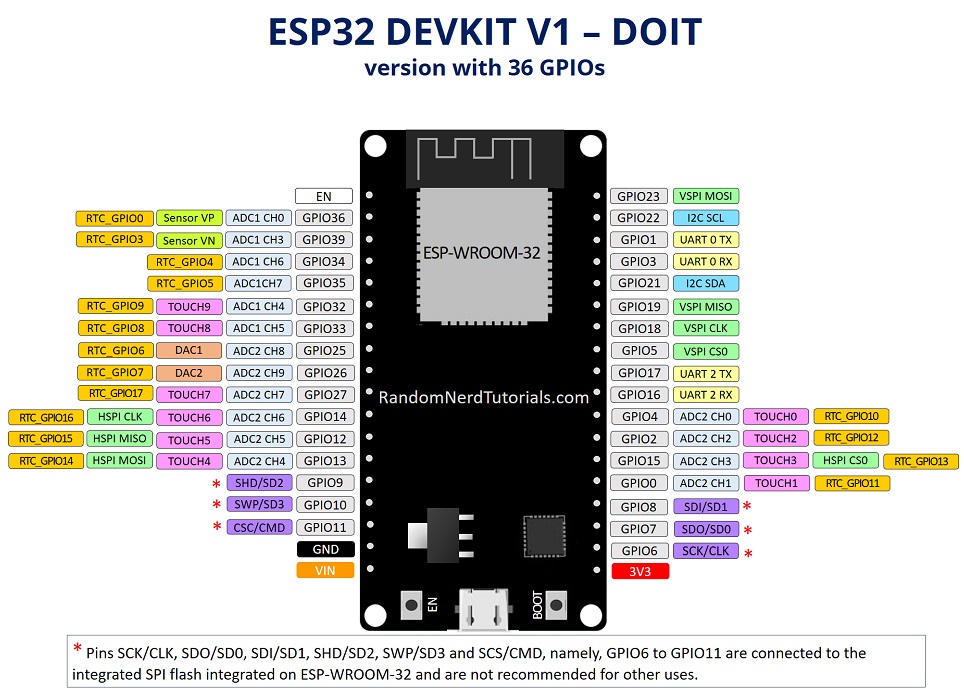
The ESP32 has more GPIOs than the ESP8266, and you can decide which pins are UART, I2CSPI—you need to set that on the code. This is possible due to the ESP32 chip’s multiplexing feature that allows you to assign multiple functions to the same pin.

If you don’t set them on the code, they will be on the pins defined by default, as shown in the following figure (this is an example for the ESP32 DEVKIT V1 DOIT board (version with 36 GPIOS)—the pin location can change depending on the manufacturer).

To learn more about the ESP32 GPIOs and how to use them, read:

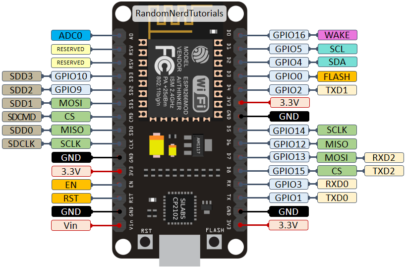
For means of comparison, here’s the pinout diagram for the ESP8266 ESP-12E NodeMCU Kit.

To learn more about the ESP8266 GPIOs and how to use them, read:

PWM, ADC, and More

You can set PWM signals in any GPIO with configurable frequencies and duty cycle set on the code.

When it comes to the analog pins, these are static, but the ESP32 supports measurements on 18 channels (analog-enabled pins) versus just one 10-bit ADC pin on the ESP8266. The ESP32 also supports two 8-bit DAC channels.

Moreover, the ESP32 contains 10 capacitive sensing GPIOs, that detect touch and can be used to trigger events, or wake-up the ESP32 from deep sleep, for example.

The ESP32 supports Bluetooth communication protocol by default, while the ESP8266 doesn’t.


Arduino IDE – ESP32 vs ESP8266

There are many ways to program the ESP32 and ESP8266 boards. Both boards can be programmed with the Arduino core using the Arduino IDE or other IDEs (like VS Code with the PlatformIO extension).

These are good news, especially for those used to program the Arduino board and are familiar with the Arduino “programming language”.

Getting started with the ESP32 or ESP8266 using Arduino IDE and have your first project running is very simple. You can follow these guides:

Although you can program both boards using Arduino IDE, they might not be compatible with the same libraries and functions. Some libraries are just compatible with one of the boards. This means that most of the time, your ESP8266 code will not be compatible with the ESP32. However, usually, you need to make a few modifications.

We have a dedicated list of free tutorials and projects for the ESP32 and ESP8266 boards using the Arduino IDE that you might found useful:

MicroPython Firwmare – ESP32 vs ESP8266

Another popular way of programming the ESP32 and ESP8266 boards is using MicroPython firmware.

MicroPython is a re-implementation of Python 3 targeted for microcontrollers and embedded systems. MicroPython is very similar with regular Python. So, if you already know how to program in Python, you also know how to program in MicroPython.

In MicroPython, most Python scripts are compatible with both boards (unlike when using Arduino IDE). This means that most of the time, you can use the same script for ESP32 and ESP8266.

You can get started with MicroPython firmware on the ESP32 and ESP8266 very quickly by following our free guides:

We also have a list of free projects using MicroPython with the ESP32 and ESP8266 boards:

Need Resources to Get Started?

If you want to get started with the ESP32 or ESP8266, you can take a look at our courses and projects:

ESP32 or ESP8266?

So, at this point you may be wondering: Should I get an ESP8266 or an ESP32?

It really depends on what you want to do. There is space for both boards, and both have pros and cons.

The ESP8266 is cheaper than the ESP32. Although it doesn’t have as many functionalities, it works just fine for most simple DIY IoT projects. However, it has some limitations in the GPIO mapping, and it might not have enough pins for what you intend to do. If that’s the case, you should get an ESP32.

The ESP32 is much more powerful than the ESP8266, comes with more GPIOs with multiple functions, faster Wi-Fi, and supports Bluetooth. However, many people think that the ESP32 is more difficult to deal with than the ESP8266 because it is more complex. On the contrary, in our opinion, it is as easy to program the ESP32 as the ESP8266, especially if you intend to program it using the “Arduino language” or MicroPython.

The ESP32 has some cons too. The ESP32 is more expensive than the ESP8266. So, if you’re building a simple IoT project, the ESP8266 might do the trick for a lower price. Additionally, because the ESP8266 is “older” than the ESP32, some libraries and features are better developed for the ESP8266, and you’ll find more resources (forums, people with the same issues, and how to solve them, etc.). However, as time goes by, the ESP32 is being widely adopted, and these differences in terms of development and libraries won’t be noticeable.

My personal experience: in 2021, I use almost exclusively the ESP32 for IoT projects. It is more versatile, and it comes with much more functionalities like Bluetooth, different wake-up sources, many peripherals, and much more. Additionally, the price difference is not a big deal, in my opinion. Once you move to the ESP32, you won’t want to go back to the ESP8266.

Wrapping Up

We hope you’ve found our analysis ESP32 vs ESP8266 useful.

Just to wrap up the main differences between the ESP32 and ESP8266:

  • The ESP32 is faster than the ESP8266;
  • The ESP32 comes with more GPIOs with multiple functions;
  • The ESP32 supports analog measurements on 18 channels (analog-enabled pins) versus just one 10-bit ADC pin on the ESP8266;
  • The ESP32 supports Bluetooth while the ESP8266 doesn’t;
  • The ESP32 is dual-core, and the ESP8266 is single core;
  • The ESP8266 is cheaper than the ESP32;
  • The ESP8266 has a wider community (although we don’t think that at this point, the difference is that relevant);
  • For many IoT and Wi-Fi projects, the ESP8266 can do the job for a lower price;
  • Both boards can be programmed with the Arduino core using Arduino IDE or other supported IDEs.
  • Both boards support MicroPython firmware.

You might like reading the following ESP8266 and ESP32 related articles to have an idea of the selection of the most popular ESP32 and ESP8266 development boards:

So, if you’re a beginner, should you get started with the ESP32 or the ESP8266? At this point, we definitely recommend getting started with the ESP32 instead of the ESP8266. However, if you already have an ESP8266 board, you can get started with that board and then make the shift to the ESP32.

We have a vast selection of projects with these boards in the Random Nerd Tutorials blog to help you get started:

Thanks for reading.

Docker OpenWrt Builder

Docker OpenWrt Builder

Build OpenWrt images in a Docker container. This is sometimes necessary when building OpenWrt on the host system fails, e.g. when some dependency is too new. The docker image is based on Debian 10 (Buster).

Build tested:

  • OpenWrt-21.02.2
  • OpenWrt-19.07.8
  • OpenWrt-18.06.9

A smaller container based on Alpine Linux is available in the alpine branch. But it does not build the old LEDE images.

Prerequisites

  • Docker installed
  • running Docker daemon
  • build Docker image:
git clone https://github.com/strongkill/docker-openwrt-builder.git
cd docker-openwrt-builder
docker build -t openwrt_builder .

Now the docker image is available. These steps only need to be done once.

Usage GNU/Linux

Create a build folder and link it into a new docker container:

mkdir ~/mybuild
docker run -v ~/mybuild:/home/user -it openwrt_builder /bin/bash

In the container console, enter:

git clone https://git.openwrt.org/openwrt/openwrt.git
cd openwrt
./scripts/feeds update -a
./scripts/feeds install -a
make menuconfig
make -j4

After the build, the images will be inside ~/mybuild/openwrt/bin/target/.

Usage MacOSX

OpenWrt requires a case-sensitive filesystem while MacOSX uses a case-insensitive filesystem by default.

Create a disk image:

hdiutil create -size 20g -fs "Case-sensitive HFS+" -volname OpenWrt OpenWrt.dmg 
hdiutil attach OpenWrt.dmg

Then run:

docker run -v /volumes/openwrt:/home/user -it openwrt_builder /bin/bash

(Source)

Usage Windows

TODO

Other Projects

Other, but very similar projects:

IAR for STM8的簡介、下載、安裝及註冊教程

一、簡介

1.關於IAR for STM8

IAR for STM8 是一個嵌入式工作平台,主要應用於STM8 系列芯片的開發,現在(2018年3.10版本)能夠支持市面上所有的STM8芯片。

個人認為,IAR for STM8和Keil差別並不是很大,只要熟悉Keil的使用,那上手IAR for STM8並不是什麼難事,網絡上也有許多相關資料可以查詢。

2.關於該篇博客

這一篇博客主要來講解一下IAR的下載、安裝、註冊的步驟,

雖然說的是IAR for STM8的教程,

但其實ARM跟其他的下載、安裝步驟類似的。

大家可以從我的百度雲下載IAR for STM8(3.10版本)和註冊機!!!

鏈接:https://pan.baidu.com/s/16UHwCZkgONEeLwiwBawAhg
提取碼:gvj9 

二、下載IAR for STM8軟件(以下兩種下載方法均可)

1.從官網下載

網址:https://www.iar.com/iar-embedded-workbench/#!?architecture=STM8

2.百度雲下載

鏈接:https://pan.baidu.com/s/1KU6QKuLZXysiwo9J_b0fPQ
提取碼:3nf0 


三、安裝IAR for STM8軟件

軟件安裝就比較簡單了,這裡就沒什麼難的地方~

只要從一開始的這個界面,一直點“next”、“yes”、“是”……就能順利安裝完成~

安裝完成後進入軟件界面,如下:


 四、軟件註冊

1.打開軟件IAR Embedded Workbench IDE:License Manager ->“取消”->“確定”

License Manager:


“取消”:


“確定”:

2.許可管理License Manager:“License”->“Offline Activation”(離線激活) ->“License Wizard”

License Manager:


點擊“License”->“Offline Activation” :


License Wizard:

3.打開註冊機: 選STM8->生成許可碼->複製


選擇STM8:


生成(Generate):


複製:

4.激活界面:黏貼->下一步->……


選擇“No” :


選擇存儲路徑:


放在此路徑下:


請求激活信息界面:

5.註冊機:選擇剛才存儲的文件->


點擊後生成新的文件:


再選取新生成的文件:


點擊下一步:

6.檢查註冊狀況:

雙擊: 


顯示狀態都是“ok”,那就恭喜註冊成功!!!

事到如今,IAR for STM8 已經完全可以使用了。

希望能幫助到有需要的朋友~


micropython ESP32 SOLO-1 firmware binary

E (469) cpu_start: Running on single core chip, but application is built with dual core support.
E (478) cpu_start: Please enable CONFIG_FREERTOS_UNICORE option in menuconfig.
microPython Enable dual core support by default.
Single core is still supported, just by adding CONFIG_FREERTOS_UNICORE=y to
a custom sdkconfig file.

for ESP32 SOLO-1 you may do this.

modify file ports/esp32/boards/sdkconfig.base and add:

# FreeRTOS
CONFIG_FREERTOS_UNICORE=y

it should be ok to run in unicore mode on a dual core.

or Download this binary file.

build-GENERIC.zip

#esptool.py -p {PORT} -b 460800 --before default_reset --after hard_reset --chip esp32 write_flash --flash_mode dio --flash_size detect --flash_freq 40m 0x1000 build-GENERIC/bootloader/bootloader.bin 0x8000 build-GENERIC/partition_table/partition-table.bin 0x10000 build-GENERIC/micropython.bin

我的第一個STM32程式,使用Arduino IDE 介面

rduino已經用了很長的一段時間,有些與 Arduino 相容開發板的延伸應用,如 NodeMCU、ESP32 等,實作了一些相關的控制。當時覺得 STM32 可能與 Arduino 類似,就沒特別想買一個來練習。這次在看了 STM32 的規格後,覺得比 Arduino 強很多,也可以使用 Arduino IDE 來撰寫 STM32 程式,利用購買一批電子零件的機會,順便買了一片 STM32F103C8T6 開發板,來測試一下這片開發板的功能。

我整理一下 Arduino Uno 的 ATmega328 與 Mega 使用的 ATmega2560 以及 STM32 三個微控制器的比較,可以看到 STM32 的 32bit 處理器及其他規格都比 Arduino Uno 或 Mega 要強很多。一般如果是用在做玩具或啟蒙電子教育功能,Arduino 比較適合,如果是要做成工業或商用產品,那 STM32 會更好。

編號 規格 STM32F103C8 ATMEGA328 ATMEGA2560
1 CPU 32 Bit 8 Bit 8 Bit
2 CPU clock [MHz] 72 16 16
3 Flash [KB] 64 / 128 32 256
4 RAM [KB] 20 2 8
5 ADC Channels 10 8 16
6 ADC Resolution [bits] 12 10 10
7 ADC Sampling Frequency [KHz] 1000 10 / 15.38 max 15
8 PWM Channels 20 6 15
9 SPI 2 2 5
10 I2C 2 1 1
11 USB 1 0 0
這是 STM32 的引腳排列資料:

剛開始使用 STM32 時,我以為連接的方式會跟 Arduino 一樣,直接拉一條 USB 線連接電腦跟STM32,看一下裝置管理員,無法正常安裝驅動程式,Google一下網路上的方法,是要用 TTL轉 USB 來連接電腦,於是拿出先前購買來設定 ESP01 的 CP2102,找了網路的說明,試著上傳第一個 LED 燈閃爍程式,試了幾次錯誤後,終於成功了。以下就記錄一下實際安裝的過程。

[材料]

  • USB轉TTL序列傳輸線 CP2102
  • STM32F103C8T6開發板
  • 排線 x4 條

[接線圖]

CP2102 STM32F103C8T6
GND GND
3V3 3.3V
RX PA9
TX PA10

[安裝STM32程式庫及設定]

要在Arduino IDE撰寫STM32程式,需要安裝STM32程式庫,這個設定方法跟ESP8266很像。開啟Arduino IDE,選擇 [檔案 File] → [偏好設定 Preferences ],在 [額外的開板管理員網址:] 輸入以下網址:

http://dan.drown.org/stm32duino/package_STM32duino_index.json

如下圖:

接著在Arduino IDE畫面選擇 [工具 Tools] → [開發板 Board] → [開發板管理員 Boards manager…],在搜尋的地方輸入「STM32」,如以下畫面:

在STM32F1xx/GD32F1xx Boards選項右下方按 [安裝 Install]進行程式庫安裝。

完成後,回到主畫面設定開發板:選擇 [工具 Tools] → [開發板 Board] → [STM32F1 Board(STM32duino)] → [Generic STM32F103C6 / fake STM32F103C8] 。

接著設定 CP2102 連線埠,可以先看一下裝置管理員的驅動程式是否正常,並取得連線埠資訊,如下圖紅框處:

回到 Arduino IDE 設定:選擇 [工具 Tools] → [Upload method:”Serial”] → [Serial]。

繼續設定連接序列埠:選擇 [工具 Tools] → [序列埠: Port] → [COM6]。這裡的COM6,依每台電腦不同的連線埠而更改。

設定完成後,還有個地方要調整,就是主板上有兩個Jump,其中一個 Boot0 要調整 Jump 設定為DFU模式,從預設的0位置,改到1。如下圖紅框處。而 BOOT Jump 設定具有不同的模式,等之後比較熟悉 STM32 後,再另外解釋其功能。

我要上傳程式時,發現會卡在這個地方時,只要重新按上圖黃色框處的白色 RESRT按鍵,重新起動,即可順利上傳。

上傳程式成功的畫面如下:

[程式]

這個程式會讓LED燈每秒閃爍一次,串列埠視窗會印出”Hello World”。

#define pinLED PC13

void setup() {
  Serial.begin(9600);
  pinMode(pinLED, OUTPUT);
}

void loop() {
  digitalWrite(pinLED, HIGH);
  delay(1000);
  digitalWrite(pinLED, LOW);
  delay(1000);
  Serial.println("Hello World");  
}

[實作結果]

執行的影片如下:

開啟串列埠的視窗:

How to Use a Joystick with Serial Monitor

This project will show you how to use joystick with serial monitor.

Operation and uses


The joystick is similar to two potentiometers connected together, one for the vertical movement (Y-axis) and other for the horizontal movement (X-axis).


The potentiometers are variable resistances and, in a way, they act as sensors that provide us with varying voltage depending on their rotation.

Generally, joysticks are used in the military, leisure and aviation sectors.


Using the joystick pins


VCC

GND

VRx -> Variable resistance x

VRY -> Variable resistance Y

SW -> Switch / Button

Connection

MODULE -> ARDUINO

  • VCC -> 5V
  • GND -> GND
  • VRx -> A0
  • VRy -> A1
  • SW -> Pin 2
int VRx = A0;
int VRy = A1;
int SW = 2;

int xPosition = 0;
int yPosition = 0;
int SW_state = 0;
int mapX = 0;
int mapY = 0;

void setup() {
  Serial.begin(9600); 
  
  pinMode(VRx, INPUT);
  pinMode(VRy, INPUT);
  pinMode(SW, INPUT_PULLUP); 
  
}

void loop() {
  xPosition = analogRead(VRx);
  yPosition = analogRead(VRy);
  SW_state = digitalRead(SW);
  mapX = map(xPosition, 0, 1023, -512, 512);
  mapY = map(yPosition, 0, 1023, -512, 512);
  
  Serial.print("X: ");
  Serial.print(mapX);
  Serial.print(" | Y: ");
  Serial.print(mapY);
  Serial.print(" | Button: ");
  Serial.println(SW_state);

  delay(100);
  
}

Arduino Nano CNC Shield V4 with grbl PIN ERROR

The CNC Shield V4 came with some factory errors being a cloned version for china, the step puls and step direction pin numbers have been alternated, this article also show how to correct it. Just modify one file.

modify cpu_map.h file at line 39

#define X_STEP_BIT 5 // Uno Digital Pin 2
#define Y_STEP_BIT 6 // Uno Digital Pin 3
#define Z_STEP_BIT 7 // Uno Digital Pin 4

and line 47

#define X_DIRECTION_BIT 2 // Uno Digital Pin 5
#define Y_DIRECTION_BIT 3 // Uno Digital Pin 6
#define Z_DIRECTION_BIT 4 // Uno Digital Pin 7


save and exit

recompile and upload firmware

and done.

How to Use MQTT With the Raspberry Pi and ESP8266

How to Use MQTT With the Raspberry Pi and ESP8266

In this Instructable, I will explain what the MQTT protocol is and how it is used to communicate between devices.Then, as a practical demonstration, I shall show you how to setup a simple two client system, where an ESP8266 module will send a message to a Python program when a button is pushed. Specifically, I am using an Adafruit HUZZAH module for this project, a Raspberry Pi and a desktop computer. The Raspberry Pi will be acting as the MQTT broker, and the Python client will be run from a separate desktop computer (optional, as this could be run on the Raspberry Pi).

To follow along with this Instructable, you will need to have some basic knowledge of electronics, and how to use the Arduino software. You should also be familiar with using a command line interface (for the Raspberry Pi). Hopefully, once you’ve gained the knowledge of what MQTT is, and how to use it in a basic scenario, you will be able to create your own IoT projects!

Required Parts

  • 1 x Raspberry Pi, connected to a local network (running Jessie)
  • 1 x ESP8266 Module (Adafruit HUZZAH)
  • 1 x Breadboard
  • 3 x Jumper Wires (Male-to-Male)
  • 1 x Pushbutton
  • 1 x 10k Ohm Resistor (Brown-Black-Orange colour code)

I’ve created this Instructable, as MQTT has always interested me as a protocol and there are many different ways it could be used. However, I couldn’t seem to get my head around how to code devices to use it. This was because I didn’t know/understand what was actually going on to take my “Hello, World!” from device A and send it to device B. Hence, I decided to write this Instructable to (hopefully) teach you how it works, and to also reinforce my own understanding of it!


Step 1: What Is MQTT?

What Is MQTT?

MQTT, or MQ Telemetry Transport, is a messaging protocol which allows multiple devices to talk to each other. Currently, it is a popular protocol for the Internet of Things, although it has been used for other purposes – for example, Facebook Messenger. Interestingly MQTT was invented in 1999 – meaning it’s as old as me!

MQTT is based around the idea that devices can publish or subscribe to topics. So, for example. If Device #1 has recorded the temperature from one of its sensors, it can publish a message which contains the temperature value it recorded, to a topic (e.g. “Temperature”). This message is sent to an MQTT Broker, which you can think of as a switch/router on a local area network. Once the MQTT Broker has received the message, it will send it to any devices (in this case, Device #2) which are subscribed to the same topic.

In this project, we will be publishing to a topic using an ESP8266, and creating a Python script that will subscribe to this same topic, via a Raspberry Pi which will act as the MQTT Broker. The great thing about MQTT is that it is lightweight, so it perfect for running on small microcontrollers such as an ESP8266, but it is also widely available – so we can run it on a Python script as well.

Hopefully, at the end of this project, you will have an understanding of what MQTT is and how to use it for your own projects in the future.

Step 2: Installing the MQTT Broker on the Raspberry Pi

Installing the MQTT Broker on the Raspberry Pi

To setup our MQTT system, we need a broker, as explained in the previous step. For the Raspberry Pi, we will be using the “Mosquitto” MQTT broker. Before we install this, it is always best to update our Raspberry Pi.

sudo apt-get update
sudo apt-get upgrade

Once you’ve done this, install mosquitto and then the mosquitto-clients packages.

sudo apt-get install mosquitto -y
sudo apt-get install mosquitto-clients -y

When you’ve finished installing these two packages, we are going to need to configure the broker. The mosquitto broker’s configuration file is located at /etc/mosquitto/mosquitto.conf, so open this with your favourite text editor. If you don’t have a favourite text editor or don’t know how to use any of the command line editors, I’ll be using nano so you can follow along:

sudo nano /etc/mosquitto/mosquitto.conf

At the bottom of this file, you should see the line:

include_dir /etc/mosquitto/conf.d

Delete this line. Add the following lines to the bottom of the file.

allow_anonymous false
password_file /etc/mosquitto/pwfile
listener 1883

By typing those lines, we’ve told mosquitto that we don’t want anyone connecting to our broker who doesn’t supply a valid username and password (we’ll get on to set these in a second) and that we want mosquitto to listen for messages on port number 1883.

If you don’t want the broker to require a username and password, don’t include the first two lines that we added (i.e. allow_anonymous… and password_file…). If you have done this, then skip to rebooting the Raspberry Pi.

Now close (and save) that file. If you are following along with the nano example, press CTRL+X, and type Y when prompted.

Because we’ve just told mosquitto that users trying to use the MQTT broker need to be authenticated, we now need to tell mosquitto what the username and password are! So, type the following command – replacing username with the username that you would like – then enter the password you would like when prompted (Note: if, when editing the configuration file, you specified a different password_file path, replace the path below with the one you used).

sudo mosquitto_passwd -c /etc/mosquitto/pwfile username

As we’ve just changed the mosquitto configuration file, we should reboot the Raspberry Pi.

sudo reboot

Once the Raspberry Pi has finished rebooting, you should have a fully functioning MQTT broker! Next, we are going to try to interact with it, using a number of different devices/methods!

Step 3: Testing the Broker

Testing the Broker

Once you’ve installed mosquitto on the Raspberry Pi, you can give it a quick test – just to make sure everything is working correctly. For this purpose, there are two commands that we can use on the command line. mosquitto_pub and mosquitto_sub. In this step, I will guide you through using each of these to test our broker.

In order to test the broker, you will need to open two command line windows. If you are using Putty or another SSH client, this is as simple as opening another SSH window and logging in as usual. If you are accessing your Pi from a UNIX terminal, this is exactly the same. If you are using the Raspberry Pi directly, you will need to open two terminal windows in the GUI mode (the command startxcan be used to start the GUI).

Now that you have opened two windows, we can get started on the testing. In one of the two terminals, type the following command, replacing username and password with the ones you setup in the previous step.

mosquitto_sub -d -u username -P password -t test

If you decided not to set a username and password in the previous step, then from now on, ignore the -u and -P flags in the commands. So, as an example, the mosquitto_sub command would now be:

mosquitto_sub -d -t test

The mosquitto_sub command will subscribe to a topic, and display any messages that are sent to the specified topic in the terminal window. Here, -d means debug mode, so all messages and activity will be output on the screen. -u and -P should be self-explanatory. Finally, -t is the name of the topic we want to subscribe to – in this case, “test”.

Next, in the other terminal window, we are going to try and publish a message to the “test” topic. Type the following, remembering again to change username and password:

mosquitto_pub -d -u username -P password -t test -m "Hello, World!"

When you press enter, you should see your message “Hello, World!” appear in the first terminal window we used (to subscribe). If this is the case, you’re all set to start working on the ESP8266!

Step 4: Setting Up the ESP8266 (Adafruit HUZZAH)

Setting Up the ESP8266 (Adafruit HUZZAH)

This step if specific to the Adafruit HUZZAH (as that is what I am using to complete this project). If you are using a different Arduino / ESP8266 device, you may wish to skip this step. However, I would advise you skim read it, just in case there is any information here that may be relevant to you.

For this project, I am going to be programming the HUZZAH with the Arduino software. So, if you haven’t already, make sure to install the Arduino software (newer than 1.6.4). You can download it here.

Once you have installed the Arduino software, open it and navigate to File->Preferences. Here you should see (near the bottom of the window) a text box with the label: “Additional Boards Manager URLs”. In this text box, copy and paste the following link:

http://arduino.esp8266.com/stable/package_esp8266com_index.json

Click OK to save your changes. Now open the Board Manager (Tools->Board->Board Manager) and search for ESP8266. Install the esp8266 by ESP8266 Community package. Restart the Arduino software.

Now, before we can program the board, we need to select a few different options. In the Tools menu option, select Adafruit HUZZAH ESP8266 for Board, 80 MHz for the CPU Frequency (you can use 160 MHz if you wish to overclock it, but for now I’m going to use 80 MHz), 4M (3M SPIFFS) for the Flash Size, and 115200 for the Upload Speed. Also, make sure to select the COM port that you are using (this will depend on your setup).

Before you can upload any code, you need to make sure that the HUZZAH is in bootloader mode. To enable this, hold down the button on the board marked GPIO0, and whilst this is held, hold down the Reset button as well. Then, release the Reset button, and then GPIO0. If you have done this correctly, the red LED that came on when you pressed GPIO0 should now be dimly lit.

To upload code to the microcontroller, first make sure the HUZZAH is in bootloader mode, then simply click the upload button in the Arduino IDE.

If you are having any trouble setting up the HUZZAH, further information can be found at Adafruit’s own tutorial.

Step 5: Programming the ESP8266

Programming the ESP8266

Now we will begin to program the ESP8266, but before we can start, you will need to install the following libraries in the Arduino Library manager (Sketch->Include Libraries->Manage Libraries)

  • Bounce2
  • PubSubClient

Once you’ve installed those libraries, you will be able to run the code I’ve included in this Instructable (MQTT_Publish.zip). I’ve made sure to comment it so that you can understand what each section is doing, and this should hopefully enable you to adapt it to your needs.

Remember to change the constants at the top of the code so that your ESP8266 can connect to your WiFi network and your MQTT Broker (the Raspberry Pi).

If you decided not to set a username and password for the MQTT Broker, then download the MQTT_PublishNoPassword.zip file instead.

Attachments

Step 6: Installing Python Client (paho-mqtt)

Installing Python Client (paho-mqtt)

Thankfully, this step is very simple! To install the mosquitto python client, you just need to type the following into the command line (Linux/Mac) or even command prompt (Windows).

pip install paho-mqtt

Note: Windows command prompt may have an issue running the pip command if you didn’t specify that you wanted pip installed and python added to your PATH variable when you installed Python. There are a number of ways of fixing this, but I think just reinstalling Python is the easiest way. If in doubt – give it a google!

Step 7: Python Client – Subscribing

Python Client - Subscribing

In this step, we are going to setup the Python script (either on the Raspberry Pi itself or on another computer connected to the network) to handle all of the messages that are sent (published) by the ESP8266 to the MQTT topic.

I have included the python code below (PythonMQTT_Subscribe.py), which has been commented to help you understand what is going on, but I will explain some of the main features here as well.

If you didn’t set a username and password for the MQTT connection earlier, download the PythonMQTT_SubscribeNoPassword.py file instead.

Attachments

Step 8: Communicating Between ESP8266 Devices

Communicating Between ESP8266 Devices

If you want to set up an IoT network, for example, you may wish to communicate between ESP8266 devices. Thankfully, this isn’t much more complex than the code we’ve written before, however, there are a couple of notable changes.

For one ESP to send data to another, the first ESP will need to publish to the topic, and the second ESP will need to subscribe to that topic. This setup will allow for a one-way conversation – ESP(1) to ESP(2). If we want ESP(2) to talk back to ESP(1), we can create a new topic, to which ESP(2) will publish, and ESP(1) will subscribe. Thankfully, we can have multiple subscribers on the same topic, so if you want to send data to a number of systems, you will only need one topic (to which they all subscribe, except the device which is sending the data, as that will be publishing).

If you need help figuring out what each device needs to do, think about the system as a room of people. If ESP(1) is publishing, you can imagine this device as a “speaker”, and any devices that are subscribing to the topic are “listeners” in this example.

I have included some example code below, which demonstrates how an ESP8266 can subscribe to a topic, and listen for certain messages – 1 and 0. If 1 is received, the on-board LED (for the HUZZAH – GPIO 0) is switched on. If 0 is received, this LED is switched off.

If you want to process more complex data, this should be done in the ReceivedMessage function (see code).

For your own projects, if you need to both send and receive data, you can incorporate the publish function from the previous example into the code included in this step. This should be handled in the main Arduino loop() function.

Remember to change the variables at the top of the code to suit your network!

IoT based Smart Irrigation System using Soil Moisture Sensor and ESP8266 NodeMCU

IoT based Smart Irrigation System using Soil Moisture Sensor and ESP8266 NodeMCUIoT based Smart Irrigation System using Soil Moisture Sensor and ESP8266 NodeMCU

Most of the farmers use large portions of farming land and it becomes very difficult to reach and track each corner of large lands. Sometime there is a possibility of uneven water sprinkles. This result in the bad quality crops which further leads to financial losses. In this scenario the Smart Irrigation System using Latest IoT technology is helpful and leads to ease of farming.

The Smart irrigation System has wide scope to automate the complete irrigation system. Here we are building a IoT based Irrigation System using ESP8266 NodeMCU Module and DHT11 Sensor. It will not only automatically irrigate the water based on the moisture level in the soil but also send the Data to ThingSpeak Server to keep track of the land condition. The System will consist a water pump which will be used to sprinkle water on the land depending upon the land environmental condition such as Moisture, Temperature and Humidity.

We previously build similar Automatic Plant Irrigation System which sends alerts on mobile but not on IoT cloud. Apart from this, Rain alarm and soil moisture detector circuit can also be helpful in building Smart Irrigation system.

Before starting, it is important to note that the different crops require different Soil Moisture, Temperature and Humidity Condition. So in this tutorial we are using such a crop which will require a soil moisture of about 50-55%. So when the soil loses its moisture to less than 50% then Motor pump will turn on automatically to sprinkle the water and it will continue to sprinkle the water until the moisture goes upto 55% and after that the pump will be turned off. The sensor data will be sent to ThingSpeak Server in defined interval of time so that it can be monitored from anywhere in the world.

Components Required

  • NodeMCU ESP8266
  • Soil Moisture Sensor Module
  • Water Pump Module
  • Relay Module
  • DHT11
  • Connecting Wires

You can buy all the components required for this project.

Circuit Diagram

Circuit diagram for this IoT Smart Irrigation System is given below:

Circuit Diagram for IoT based Smart Irrigation System using Soil Moisture Sensor and ESP8266 NodeMCU

Circuit Hardware for IoT based Smart Irrigation System using Soil Moisture Sensor and ESP8266 NodeMCU

Programming ESP8266 NodeMCU for Automatic Irrigation System

For programming the ESP8266 NodeMCU module, only the DHT11 sensor library is used as external library. The moisture sensor gives analog output which can be read through the ESP8266 NodeMCU analog pin A0. Since the NodeMCU cannot give output voltage greater than 3.3V from its GPIO so we are using a relay module to drive the 5V motor pump. Also the Moisture sensor and DHT11 sensor is powered from external 5V power supply.

Complete code with a working video is given at the end of this tutorial, here we are explaining the program to understand the working flow of the project.

Start with including necessary library.

#include <DHT.h>
#include <ESP8266WiFi.h>

Since we are using the ThingSpeak Server, the API Key is necessary in order to communicate with server. To know how we can get API Key from ThingSpeak you can visit previous article on Live Temperature and Humidity Monitoring on ThingSpeak.

String apiKey = "X5AQ445IKMBYW31H
const char* server = "api.thingspeak.com"; 

The next Step is to write the Wi-Fi credentials such as SSID and Password.

const char *ssid =  "CircuitDigest";     
const char *pass =  "xxxxxxxxxxx"; 

Define the DHT Sensor Pin where the DHT is connected and Choose the DHT type.

#define DHTPIN D3          
DHT dht(DHTPIN, DHT11);

The moisture sensor output is connected to Pin A0 of ESP8266 NodeMCU. And the motor pin is connected to D0 of NodeMCU.

const int moisturePin = A0;
const int motorPin = D0;

We will be using millis() function to send the data after every defined interval of time here it is 10 seconds. The delay() is avoided since it stops the program for a defined delay where microcontroller cannot do other tasks. Learn more about the difference between delay() and millis() here.

unsigned long interval = 10000;
unsigned long previousMillis = 0;

Set motor pin as output, and turn off the motor initially. Start the DHT11 sensor reading.

pinMode(motorPin, OUTPUT);
digitalWrite(motorPin, LOW); // keep motor off initally
dht.begin();

Try to connect Wi-Fi with given SSID and Password and wait for the Wi-Fi to be connected and if connected then go to next steps.

WiFi.begin(ssid, pass);
  while (WiFi.status() != WL_CONNECTED)
  {
    delay(500);
    Serial.print(".");
  }
  Serial.println("");
  Serial.println("WiFi connected");
}

Define the current time of starting the program and save it in a variable to compare it with the elapsed time.

unsigned long currentMillis = millis();

Read temperature and humidity data and save them into variables.

float h = dht.readHumidity();
float t = dht.readTemperature();

If DHT is connected and the ESP8266 NodeMCU is able to read the readings then proceed to next step or return from here to check again.

if (isnan(h) || isnan(t))
  {
    Serial.println("Failed to read from DHT sensor!");
    return;
  }

Read the moisture reading from sensor and print the reading.

moisturePercentage = ( 100.00 - ( (analogRead(moisturePin) / 1023.00) * 100.00 ) );
  Serial.print("Soil Moisture is  = ");
  Serial.print(moisturePercentage);
  Serial.println("%");

If the moisture reading is in between the required soil moisture range then keep the pump off or if it goes beyond the required moisture then turn the pump ON.

if (moisturePercentage < 50) {
    digitalWrite(motorPin, HIGH);
  }
   if (moisturePercentage > 50 && moisturePercentage < 55) {
    digitalWrite(motorPin, HIGH);
  }
 if (moisturePercentage > 56) {
    digitalWrite(motorPin, LOW);
  }

Now after every 10 seconds call the sendThingspeak() function to send the moisture, temperature and humidity data to ThingSpeak server.

  if ((unsigned long)(currentMillis - previousMillis) >= interval) {
    sendThingspeak();
    previousMillis = millis();
    client.stop();
  }

In the sendThingspeak() function we check if the system is connected to server and if yes then we prepare a string where moisture, temperature, humidity reading is written and this string will be sent to ThingSpeak server along with API key and server address.

if (client.connect(server, 80))
    {
      String postStr = apiKey;
      postStr += "&field1=";
      postStr += String(moisturePercentage);
      postStr += "&field2=";
      postStr += String(t);
      postStr += "&field3=";
      postStr += String(h);      
      postStr += "\r\n\r\n";

Finally the data is sent to ThingSpeak server using client.print() function which contains API key, server address and the string which is prepared in previous step.

client.print("POST /update HTTP/1.1\n");
      client.print("Host: api.thingspeak.com\n");
      client.print("Connection: close\n");
      client.print("X-THINGSPEAKAPIKEY: " + apiKey + "\n");
      client.print("Content-Type: application/x-www-form-urlencoded\n");
      client.print("Content-Length: ");
      client.print(postStr.length());
      client.print("\n\n");
      client.print(postStr);

Finally this is how the data looks on ThingSpeak Dashboard

Getting Data on ThingSpeak for IoT based Smart Irrigation System

This last step finishes the complete tutorial on IoT based Smart Irrigation System. Note that it is important to switch off the motor when the soil moisture has reached the required level after water sprinkle. You can make a more smart system which can contain different control for different crops.

If you face any issues while doing this project then comment below or reach to our forums for more relevant questions and their answers.

Find the complete program and demonstration Video for this project below.

Code

#include <DHT.h>
#include <ESP8266WiFi.h>
String apiKey = “X5AQ3EGIKMBYW31H”;     //  Enter your Write API key here
const char* server = “api.thingspeak.com”;
const char *ssid =  “CircuitLoop”;     // Enter your WiFi Name
const char *pass =  “circuitdigest101”; // Enter your WiFi Password
#define DHTPIN D3          // GPIO Pin where the dht11 is connected
DHT dht(DHTPIN, DHT11);
WiFiClient client;

const int moisturePin = A0;             // moisteure sensor pin
const int motorPin = D0;
unsigned long interval = 10000;
unsigned long previousMillis = 0;
unsigned long interval1 = 1000;
unsigned long previousMillis1 = 0;
float moisturePercentage;              //moisture reading
float h;                  // humidity reading
float t;                  //temperature reading

void setup()
{
Serial.begin(115200);
delay(10);
pinMode(motorPin, OUTPUT);
digitalWrite(motorPin, LOW); // keep motor off initally
dht.begin();
Serial.println(“Connecting to “);
Serial.println(ssid);
WiFi.begin(ssid, pass);
while (WiFi.status() != WL_CONNECTED)
{
delay(500);
Serial.print(“.”);              // print … till not connected
}
Serial.println(“”);
Serial.println(“WiFi connected”);
}

void loop()
{
unsigned long currentMillis = millis(); // grab current time

h = dht.readHumidity();     // read humiduty
t = dht.readTemperature();     // read temperature

if (isnan(h) || isnan(t))
{
Serial.println(“Failed to read from DHT sensor!”);
return;
}

moisturePercentage = ( 100.00 – ( (analogRead(moisturePin) / 1023.00) * 100.00 ) );

if ((unsigned long)(currentMillis – previousMillis1) >= interval1) {
Serial.print(“Soil Moisture is  = “);
Serial.print(moisturePercentage);
Serial.println(“%”);
previousMillis1 = millis();
}

if (moisturePercentage < 50) {
digitalWrite(motorPin, HIGH);         // tun on motor
}
if (moisturePercentage > 50 && moisturePercentage < 55) {
digitalWrite(motorPin, HIGH);        //turn on motor pump
}
if (moisturePercentage > 56) {
digitalWrite(motorPin, LOW);          // turn off mottor
}

if ((unsigned long)(currentMillis – previousMillis) >= interval) {

sendThingspeak();           //send data to thing speak
previousMillis = millis();
client.stop();
}

}

void sendThingspeak() {
if (client.connect(server, 80))
{
String postStr = apiKey;              // add api key in the postStr string
postStr += “&field1=”;
postStr += String(moisturePercentage);    // add mositure readin
postStr += “&field2=”;
postStr += String(t);                 // add tempr readin
postStr += “&field3=”;
postStr += String(h);                  // add humidity readin
postStr += “\r\n\r\n”;

client.print(“POST /update HTTP/1.1\n”);
client.print(“Host: api.thingspeak.com\n”);
client.print(“Connection: close\n”);
client.print(“X-THINGSPEAKAPIKEY: ” + apiKey + “\n”);
client.print(“Content-Type: application/x-www-form-urlencoded\n”);
client.print(“Content-Length: “);
client.print(postStr.length());           //send lenght of the string
client.print(“\n\n”);
client.print(postStr);                      // send complete string
Serial.print(“Moisture Percentage: “);
Serial.print(moisturePercentage);
Serial.print(“%. Temperature: “);
Serial.print(t);
Serial.print(” C, Humidity: “);
Serial.print(h);
Serial.println(“%. Sent to Thingspeak.”);
}
}

ADS1115 analog-to-digital converter and ESP8266

The ADS1115 device is a precision, low-power, 16-bit, I2C-compatible, analog-to-digital converters (ADCs) offered in an ultra-small, leadless, X2QFN-10 package, and a VSSOP-10 package. The ADS1115 device incorporates a low-drift voltage reference and an oscillator. The ADS1115 also incorporate a programmable gain amplifier and a digital comparator. These features, along with a wide operating supply range, make the ADS1115 well suited for power- and space-constrained, sensor measurement applications.

The ADS1115 perform conversions at data rates up to 860 samples per second (SPS). The PGA offers input ranges from ±256 mV to ±6.144 V, allowing precise large- and small-signal measurements. The ADS1115 features an input multiplexer  that allows two differential or four single-ended input measurements. Use the digital comparator in the ADS1115 for under- and overvoltage detection.

The ADS1115 operates in either continuous-conversion mode or single-shot mode. The devices are automatically powered down after one conversion in single-shot mode; therefore, power consumption is significantly reduced during idle periods.

Features

Wide Supply Range: 2.0 V to 5.5 V
Low Current Consumption: 150 µA
(Continuous-Conversion Mode)
Programmable Data Rate: 8 SPS to 860 SPS
Single-Cycle Settling
Internal Low-Drift Voltage Reference
Internal Oscillator
I2C Interface: Four Pin-Selectable Addresses
Four Single-Ended or Two Differential Inputs (ADS1115)
Programmable Comparator (ADS1114 and ADS1115)
Operating Temperature Range: –40°C to +125°C

Parts List

This module will cost less than $2

Amount Part Type
1 ADS1115
1 Wemos D1 mini V2


Schematics/Layout


In the layout below we just show basic connection between Wemos Mini and ADS1115 – you can add a pot, connect an LDR to one of the A0 – A3 inputs of the ADS1115

esp8266 and ads1115
esp8266 and ads1115


Code

Again we use a library and again its an adafruit one – https://github.com/adafruit/Adafruit_ADS1X15

#include <Wire.h>
#include <Adafruit_ADS1015.h>
 
Adafruit_ADS1115 ads(0x48);
 
void setup(void)
{
Serial.begin(9600);
Serial.println("Hello!");
 
Serial.println("Getting single-ended readings from AIN0..3");
Serial.println("ADC Range: +/- 6.144V (1 bit = 3mV/ADS1015, 0.1875mV/ADS1115)");
 
ads.begin();
}
 
void loop(void)
{
int16_t adc0, adc1, adc2, adc3;
 
adc0 = ads.readADC_SingleEnded(0);
adc1 = ads.readADC_SingleEnded(1);
adc2 = ads.readADC_SingleEnded(2);
adc3 = ads.readADC_SingleEnded(3);
Serial.print("AIN0: ");
Serial.println(adc0);
Serial.print("AIN1: ");
Serial.println(adc1);
Serial.print("AIN2: ");
Serial.println(adc2);
Serial.print("AIN3: ");
Serial.println(adc3);
Serial.println(" ");
 
delay(1000);
}


Links

http://www.ti.com/lit/ds/symlink/ads1115.pdf

I2C ADS1115 16 Bit ADC 4 channel Module with Programmable Gain Amplifier 2.0V to 5.5V RPi