rduino已經用了很長的一段時間,有些與 Arduino 相容開發板的延伸應用,如 NodeMCU、ESP32 等,實作了一些相關的控制。當時覺得 STM32 可能與 Arduino 類似,就沒特別想買一個來練習。這次在看了 STM32 的規格後,覺得比 Arduino 強很多,也可以使用 Arduino IDE 來撰寫 STM32 程式,利用購買一批電子零件的機會,順便買了一片 STM32F103C8T6 開發板,來測試一下這片開發板的功能。
| 編號 | 規格 | STM32F103C8 | ATMEGA328 | ATMEGA2560 |
|---|---|---|---|---|
| 1 | CPU | 32 Bit | 8 Bit | 8 Bit |
| 2 | CPU clock [MHz] | 72 | 16 | 16 |
| 3 | Flash [KB] | 64 / 128 | 32 | 256 |
| 4 | RAM [KB] | 20 | 2 | 8 |
| 5 | ADC Channels | 10 | 8 | 16 |
| 6 | ADC Resolution [bits] | 12 | 10 | 10 |
| 7 | ADC Sampling Frequency [KHz] | 1000 | 10 / 15.38 max | 15 |
| 8 | PWM Channels | 20 | 6 | 15 |
| 9 | SPI | 2 | 2 | 5 |
| 10 | I2C | 2 | 1 | 1 |
| 11 | USB | 1 | 0 | 0 |
剛開始使用 STM32 時,我以為連接的方式會跟 Arduino 一樣,直接拉一條 USB 線連接電腦跟STM32,看一下裝置管理員,無法正常安裝驅動程式,Google一下網路上的方法,是要用 TTL轉 USB 來連接電腦,於是拿出先前購買來設定 ESP01 的 CP2102,找了網路的說明,試著上傳第一個 LED 燈閃爍程式,試了幾次錯誤後,終於成功了。以下就記錄一下實際安裝的過程。
[材料]
- USB轉TTL序列傳輸線 CP2102
- STM32F103C8T6開發板
- 排線 x4 條
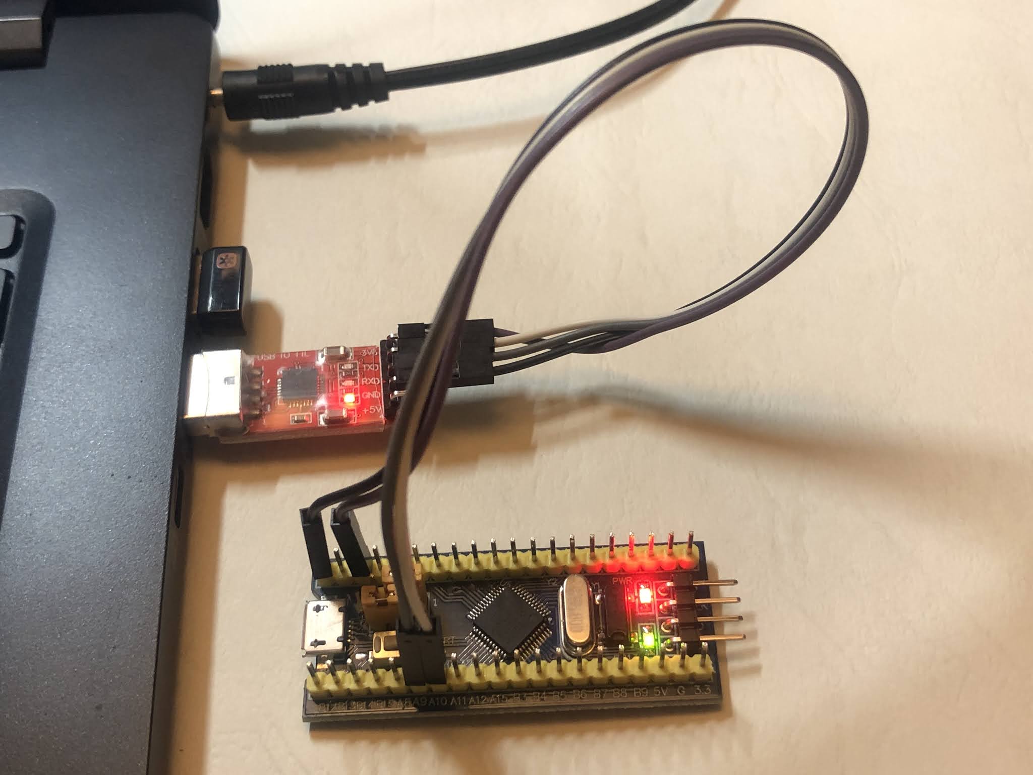
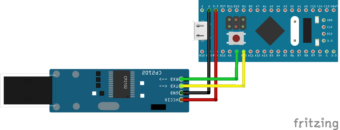
[接線圖]
| CP2102 | STM32F103C8T6 |
|---|---|
| GND | GND |
| 3V3 | 3.3V |
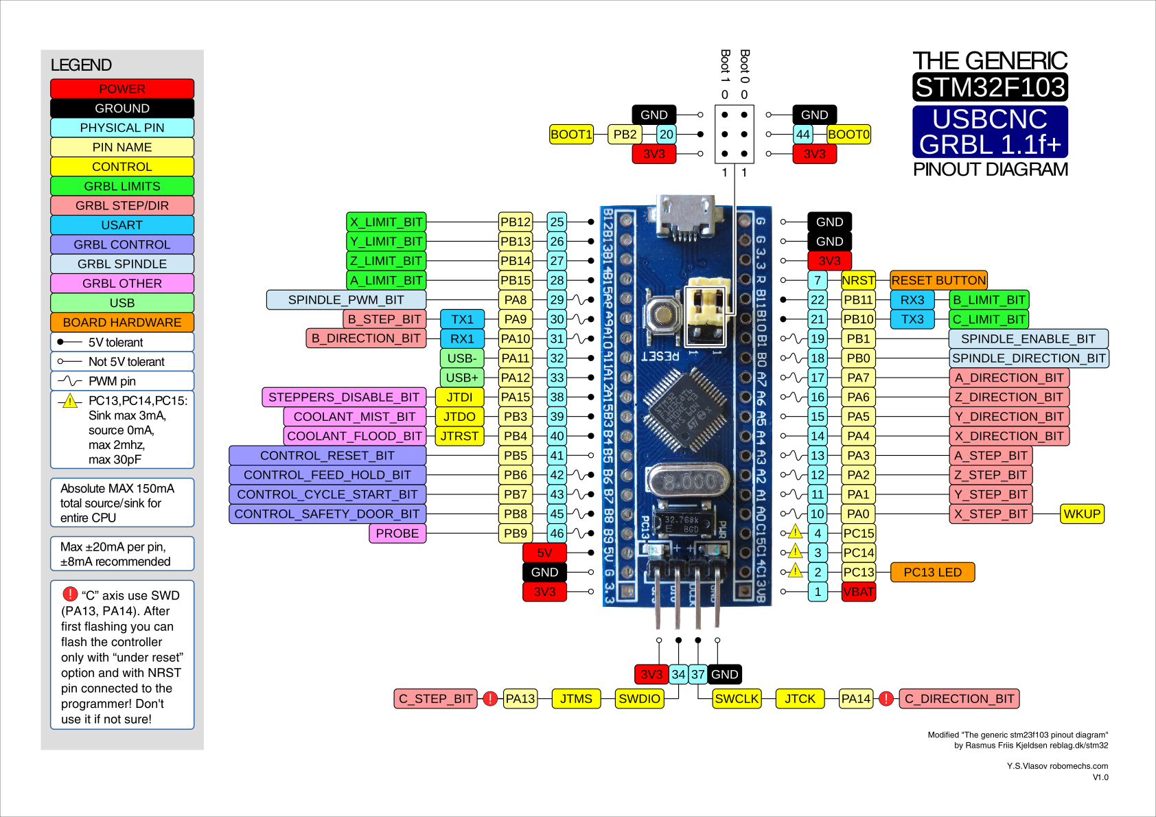
| RX | PA9 |
| TX | PA10 |
[安裝STM32程式庫及設定]
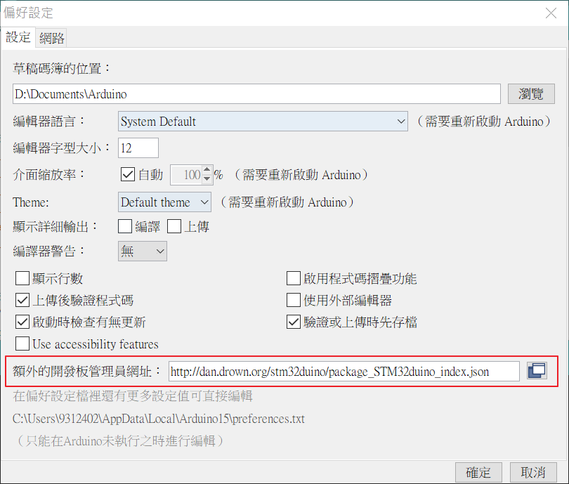
要在Arduino IDE撰寫STM32程式,需要安裝STM32程式庫,這個設定方法跟ESP8266很像。開啟Arduino IDE,選擇 [檔案 File] → [偏好設定 Preferences ],在 [額外的開板管理員網址:] 輸入以下網址:
http://dan.drown.org/stm32duino/package_STM32duino_index.json
如下圖:
接著在Arduino IDE畫面選擇 [工具 Tools] → [開發板 Board] → [開發板管理員 Boards manager…],在搜尋的地方輸入「STM32」,如以下畫面:
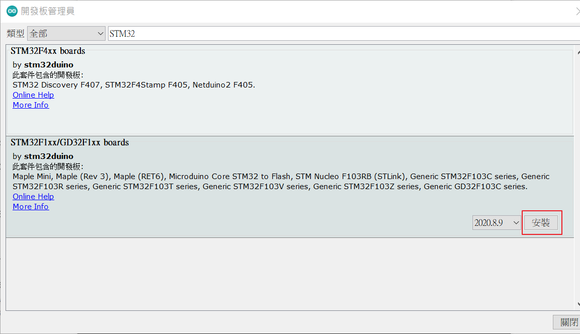
在STM32F1xx/GD32F1xx Boards選項右下方按 [安裝 Install]進行程式庫安裝。
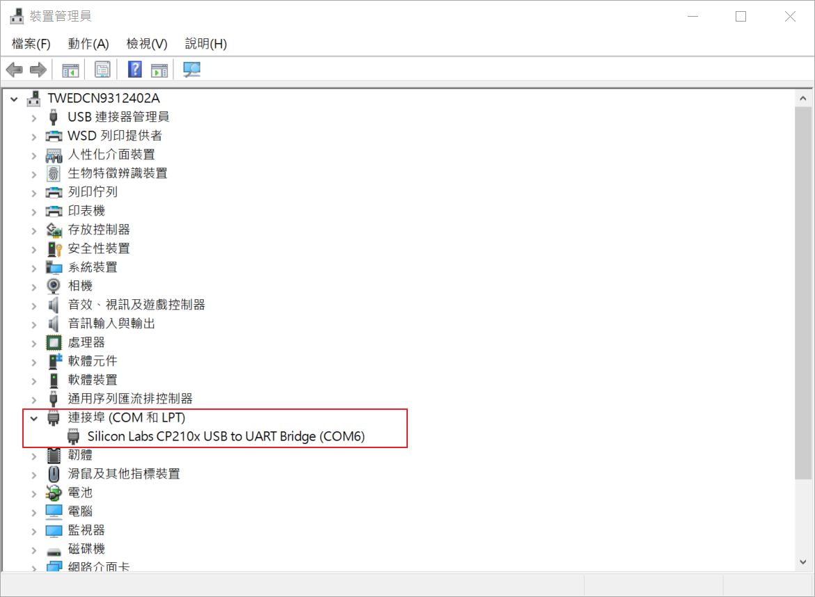
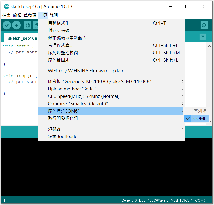
接著設定 CP2102 連線埠,可以先看一下裝置管理員的驅動程式是否正常,並取得連線埠資訊,如下圖紅框處:
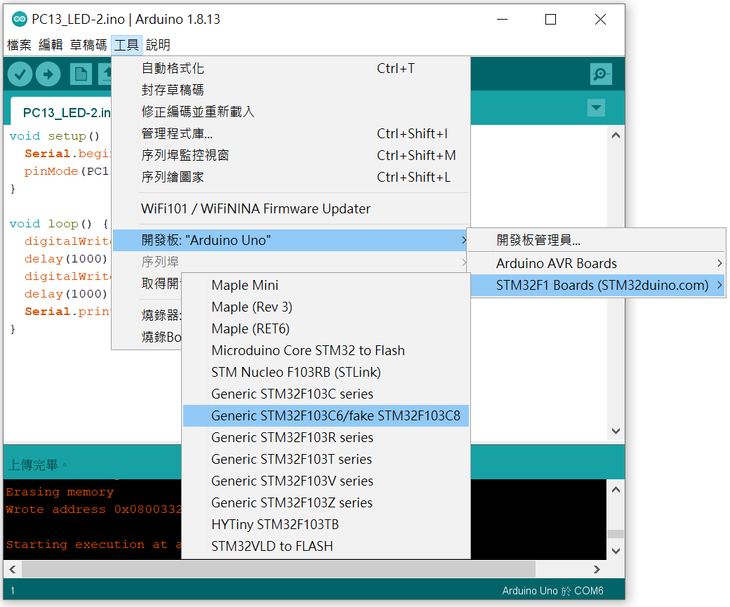
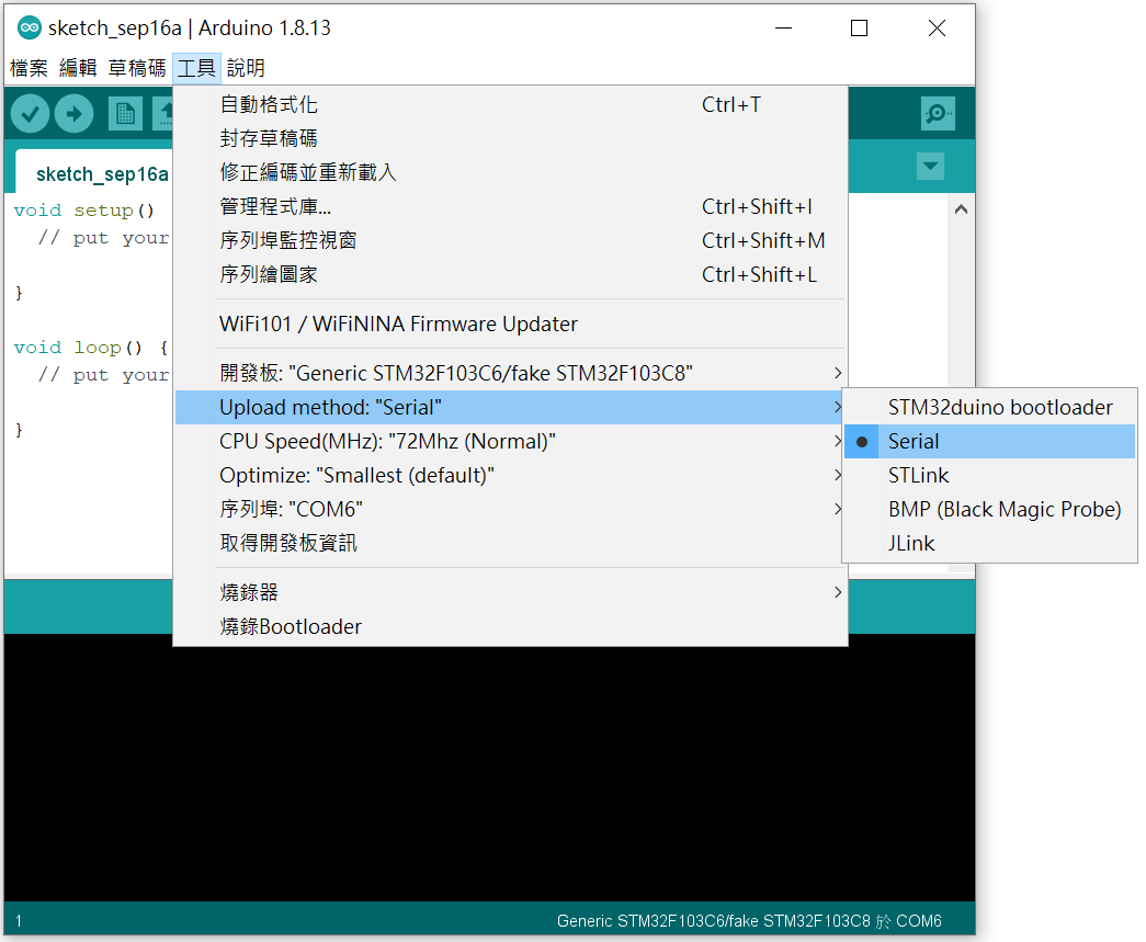
回到 Arduino IDE 設定:選擇 [工具 Tools] → [Upload method:”Serial”] → [Serial]。
設定完成後,還有個地方要調整,就是主板上有兩個Jump,其中一個 Boot0 要調整 Jump 設定為DFU模式,從預設的0位置,改到1。如下圖紅框處。而 BOOT Jump 設定具有不同的模式,等之後比較熟悉 STM32 後,再另外解釋其功能。
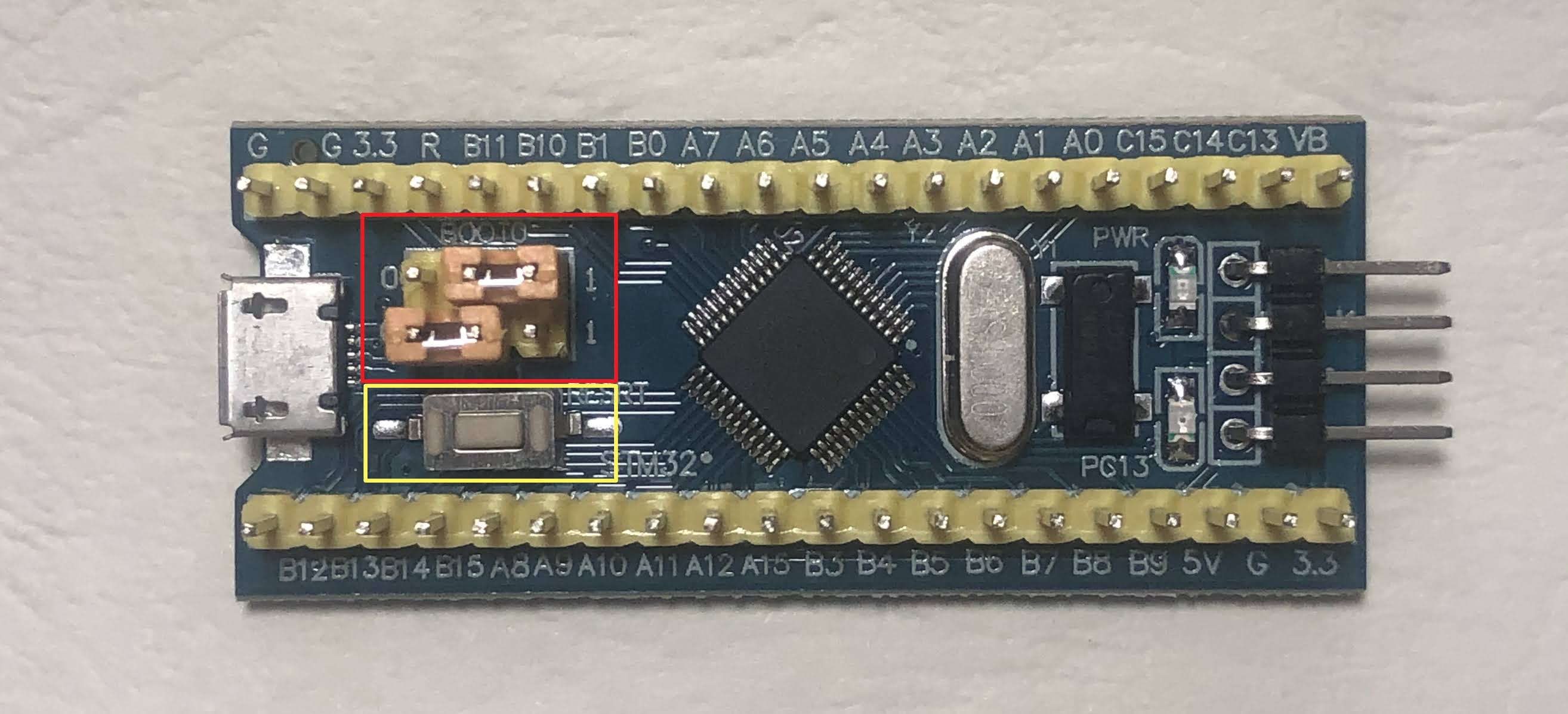
我要上傳程式時,發現會卡在這個地方時,只要重新按上圖黃色框處的白色 RESRT按鍵,重新起動,即可順利上傳。
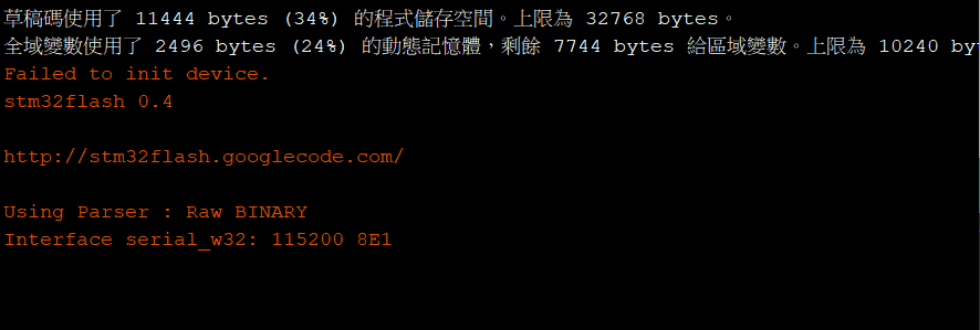
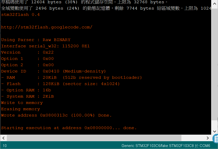
上傳程式成功的畫面如下:
[程式]
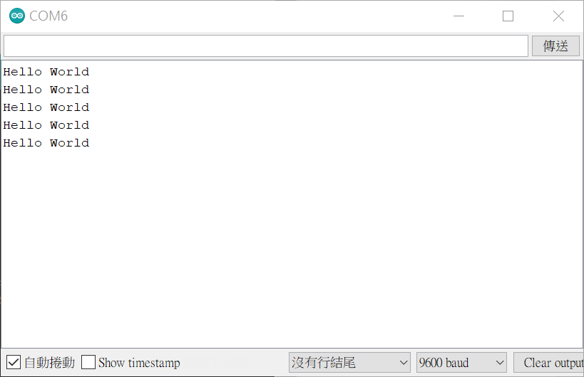
這個程式會讓LED燈每秒閃爍一次,串列埠視窗會印出”Hello World”。
#define pinLED PC13

void setup() {
  Serial.begin(9600);
  pinMode(pinLED, OUTPUT);
}

void loop() {
  digitalWrite(pinLED, HIGH);
  delay(1000);
  digitalWrite(pinLED, LOW);
  delay(1000);
  Serial.println("Hello World");
}
[實作結果]
執行的影片如下:
開啟串列埠的視窗: